SURFACE MASSES AND PTERYGIA Irregularities of the corneal surface can result from compression by external
agents, abnormalities of the corneal epithelium, or stromal alterations. Compression of the cornea can occur from eyelid lesions such as chalazia, lid
hemangiomas, and dermoids. Compressive lesions have direct as well
as indirect effects on corneal topography. There is a flattening of
the corneal curvature directly underneath the eyelid lesion and there
is a secondary indirect steepening of the corneal curvature adjacent
to the area of flattening. Scleral masses will cause scleral flattening
immediately beneath the mass and adjacent corneal steepening. Tear film disturbances and epithelial diseases that affect the tear film
canl result in topographic irregularities. The keratometer and Placido
disk systems are reflective instruments that rely on an intact air–tear
film interface. In such conditions, utilizing a projection-based
system to evaluate corneal topography may prove more accurate. Focal patches of dryness such as in keratoconjunctivitis sicca appear as
local areas of flattening. More important, however, corneal topography
can often detect subtle changes in epithelial regularity, significant
enough to cause patient complaints but not visible by slit-lamp
biomicroscopy. This has been seen in recurrent erosion syndrome and
in anterior basement membrane dystrophy (Fig. 8). A local depression such as an ulcer or dellen may produce focal
flattening. Local elevations, such as Salzmann's nodules or Thygeson's
keratitis, produce a focal steepening.1 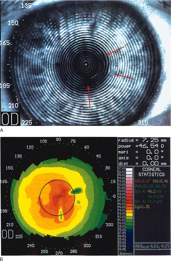 Fig. 8. Recurrent corneal erosion. In this patient with recurrent corneal erosion, no
epithelial abnormality could be detected on biomicroscopic examination
between attacks. A. The videokeratograph showed irregularity of the mires (arrows) in the 10-degree, 270-degree, and 350-degree
semimeridians, about 1 to 2 mm from the corneal center. B. These correspond to areas of focal flattening on the topography. (Corbett
MC, Rosen ES, O'Brart DPS: Corneal Topography Principles
and Applications. London, BMJ Books, 1999.) Fig. 8. Recurrent corneal erosion. In this patient with recurrent corneal erosion, no
epithelial abnormality could be detected on biomicroscopic examination
between attacks. A. The videokeratograph showed irregularity of the mires (arrows) in the 10-degree, 270-degree, and 350-degree
semimeridians, about 1 to 2 mm from the corneal center. B. These correspond to areas of focal flattening on the topography. (Corbett
MC, Rosen ES, O'Brart DPS: Corneal Topography Principles
and Applications. London, BMJ Books, 1999.)
|
Pterygia affect the corneal epithelium as well as the underlying stroma. Visual
disturbances can result from tear-film irregularity or
from growth onto the cornea, resulting in astigmatism. Both regular and
irregular astigmatism can be induced. There is progressive flattening
as the corneal periphery is approached. As the size of pterygium increases, the
amount of astigmatism and associated topographic abnormalities
increase.13–15 O'Brart and associates determined that the mean keratometric astigmatism
induced is about 4 D with-the-rule but the mean
refractive astigmatism is about 2 D.16 This does not affect refraction significantly until the pterygium head
encroaches on the visual axis (Fig. 9). There are two hypotheses regarding the mechanism of induced astigmatism. One
theory proposed by Hochbaum and associates suggests that
horizontal steepening is induced in the semi-meridian aligned
with the pterygium due to traction from subepithelial fibrosis.17 The second theory proposes that the mechanism is due to the tear film; the
tear meniscus in front of the head of the pterygium pools in the
angle between the pterygium and the paracentral cornea, leading to the
observation of topographic flattening. Pterygium removal results in decreased
astigmatism because of steepening of the flat meridian and flattening
of the steep perpendicular meridian. In eyes with large pterygia
that encroach within 2 mm of the line of sight, astigmatism may not
resolve completely. Interestingly, studies have shown that postoperatively, there
is an overall increase in mean central corneal power and
a reduction of corneal asphericity, suggesting that the ratio of the
astigmatic change in the treated meridian to that 90 degrees away was
not one-to-one. The amount of surgically induced change
in astigmatism increases with the size of the pterygium.18,19 Refractive changes stabilize 1 month postoperatively; therefore, Tomidokoro
et colleagues recommend that cataract or other refractive surgery
be postponed until this time.13,14 |
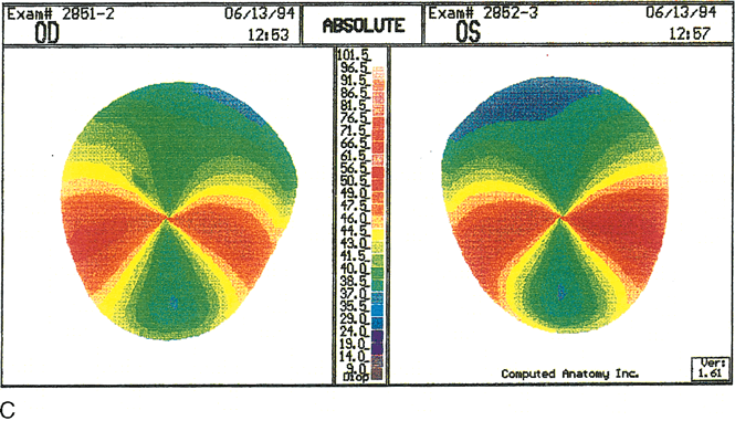
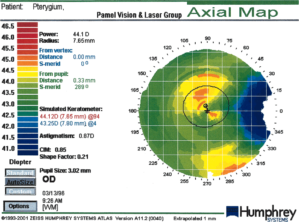 Fig. 9. Moderate pterygium. The pterygium has encroached about 3.5 mm onto the
nasal cornea. Flattening is restricted to the peripheral and paracentral
cornea, leaving only mild, regular astigmatism within the pupillary
aperture. (Courtesy of Gregory Pamel, MD.)
Fig. 9. Moderate pterygium. The pterygium has encroached about 3.5 mm onto the
nasal cornea. Flattening is restricted to the peripheral and paracentral
cornea, leaving only mild, regular astigmatism within the pupillary
aperture. (Courtesy of Gregory Pamel, MD.)
|
STROMAL ECTASIAS Crneal ectasias are non-inflammatory diseases that are characterized
by thinning and protrusion of the corneal stroma resulting in shape
changes. This family of diseases consists of keratoconus, keratoglobus, and
pellucid marginal degeneration. Normally, the stromal collagen
lamellae run circumferentially in the corneal periphery, producing a
round shape. However, progressive thinning of the stroma leads to flattening
of the corneal curvature along that meridian. This induces the
peripheral ring of collagen lamellae to assume a more oval shape and
transmits a compressive force to the lamellae that are 90 degrees away, resulting
in corneal steepening in that meridian. This mechanism is
known as biomechanical coupling. Furthermore, intraocular pressure at the site of weakness causes protrusion
of the cornea. Keratoconus Keratoconus is a bilateral but typically asymmetric ectasia that has onset
in the late teens and usually progresses slowly over many years. Patients
have a history of progressive myopia, oblique astigmatism, and
reduction of spectacle-corrected visual acuity. Prior to the introduction
of methods to assess corneal topography, the diagnosis was
based on history and the presence of clinical signs. In mild disease, however, these
clinical signs are subtle or altogether absent. The advent
of refractive surgery has made the detection of subclinical keratoconus
of increasing importance in order to prevent the surgical treatment
of these eyes. Keratoconus has an incidence of 1 in 2000 inf the
general population but is being detected in 5% of myopes who present
for refractive surgery evaluation.20 Keratoconus can be categorized according to the severity of power (mild, moderate, severe); location of cone (superior, central, inferior); and
shape of cone (oval, globus, nipple) (Fig. 10). Corneal thinning most commonly occurs in the inferocentral cornea, and
protrusion also occurs in this region. The point of maximal protrusion
is referred to as the apex of the cone. The steepest corneal
slope lies just peripheral to the apex (usually inferior in central
cones). The region of smallest radius of curvature (therefore
the greatest corneal power) lies between the cone's apex
and its steepest slope. The mechanism of biomechanical coupling causes
the flattest meridian to be approximately horizontal and the steepest
meridian to lie close to the vertical meridian. Placido disk-based
videokeratographs mirror this distortion by producing mires that
are typically oval. The distance between rings is smallest at the steepest
corneal slope and farthest apart superiorly where the cornea is
flattest. Tangential curvature maps of projection-based systems
provide additional information. On these maps the steepest slope is
easily located as being inferior to the apex, producing an asymmetric
bow tie. This corresponds to the exaggerated prolate shape of the keratoconic
eye. Projection-based systems can be used to locate the
apex of the cone on elevation maps as the highest point. The apex is
surrounded by concentric zones of decreasing elevation. A comparison of
anterior and posterior elevation maps reveals that there is a greater
change in height from periphery to central cornea posteriorly than anteriorly. On
tangential curvature maps, the apex of a cone has a slope
of zero. Protrusions such as proud nebulae also have a slope of zero. |
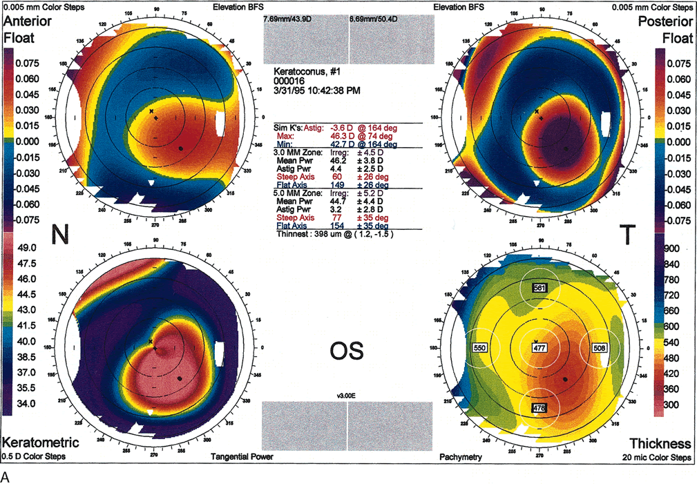 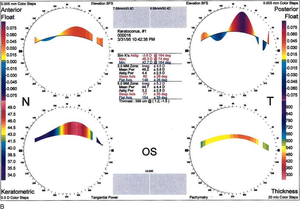 Fig. 10. A. Oval keratoconus pattern. B. Cross-sectional map through the 180-degree meridian demonstrates
maximal protrusion in the paracentral cornea with thinning in
the same area. (Orbscan, ORBTEK, Inc., Salt Lake City, Utah.)
Fig. 10. A. Oval keratoconus pattern. B. Cross-sectional map through the 180-degree meridian demonstrates
maximal protrusion in the paracentral cornea with thinning in
the same area. (Orbscan, ORBTEK, Inc., Salt Lake City, Utah.)
|
Several authors have recommended topographical indices for detecting early
keratoconus and suspected keratoconus. The diagnosis, however, still
requires the presence of Vogt's striae, a Fleischer ring, or corneal
thinning. The surface asymmetry index (SAI) measures
the irregularity of the cornea in the central 4.5-mm zone. It measures
the difference in corneal power between points on the same ring 180 degrees
apart. The inferior-superior (I-S) value
measures the average power at five superior points 3 mm from
the center at 30-degree intervals and compares this to five inferior
points 3 mm from the center at 30-degree intervals. K is
the central K-reading; when used alone, a value greater than 47.2 is
suggestive of keratoconus. The KCI%, KPI% and KISA% are
values derived by a combination of other indices. For example, the
keratoconus predictability index (KPI) combines the
SAI with seven other indices in an algorithm to predict the presence
of keratoconus with 68% sensitivity and 99% specificity. Auffarth
and co-workers. used the Orbscan to evaluate a series
of keratoconus patients and noticed that the apex and thinnest point
were located separately but with no consistent distance or pattern.20 The thinnest point was less than 0.500 mm. Furthermore, there is a high
degree of nonsuperimposable mirror-image symmetry in the location
of the cones between the right and left eyes of the same patient. The
nonsuperimposability is due to the variation in radii between the
apex and the thinnest point.20–23 Pellucid Marginal Degeneration Pellucid marginal degeneration (PMD) is another bilateral corneal-thinning
disorder. There may be asymmetry in the severity
of disease between the two eyes. Furthermore, there are reports of PMD
in one eye and keratoconus in the fellow eye. Typically in PMD, a 2-mm
wide band of thinned stroma occurs 1 to 2 mm from the inferior
limbus and spans the central four clock hours. Unlike in keratoconus, the
areas of thinning and protrusion are not the same; corneal protrusion
occurs in the cornea that lies above the area of thinning. Cases of superior PMD, nasal PMD, and circumferential
extension of inferior PMD have been recognized. Classically, in
inferior PMD topography maps the lowest corneal power to a narrow corridor
of central cornea that is close to the vertical meridian, producing
an against-the-rule astigmatism. The power increases
markedly toward the inferior periphery within this narrow corridor of
central cornea. The mires show elongation along the vertical axis with
compression inferiorly. The area of highest power extends along the inferior
cornea and then turns toward the central cornea along the inferior
oblique meridians. The term applied to this ring of high cylinder
power is the loop cylinder. Progression to the superior corneal periphery does not show an increase
in power (Fig. 11). Conversely, in superior PMD the area of highest corneal power is
in the superior periphery with extension toward the central cornea from
the superior nasal and superior temporal oblique semimeridians producing
a superior loop cylinder. If the thinning progresses toward the
horizontal, there is a shift in the meridians of highest and lowest corneal
powers. Extension of thinning nasally will cause the lowest power
to shift from the vertical toward the temporal and the highest power
to shift toward a more nasal meridian.24,25
|
Fig. 11. Pellucid marginal degeneration (PMD).
A. Slit topography showing inferior corneal thinning (arrow)
1 to 2 mm from the limbus, extending from the 5- to 8-o'clock positions
in both eyes. B. Videokeratoscopic image shows a typical
pear-shaped image with compression of the inferior rings. C.
Corneal topographic maps (absolute scale) showing against-the-rule
astigmatism of 10.6 diopters (D) in the right eye. The left eye
shows enantiomorphic symmetry (mirror image) to the right eye with
11.9 D of against-the-rule astigmatism. In early PMD the power of
the cornea is least at a vertical axis very close to 90 degrees.
The area of greater power is presented in a bow-tie configuration
of two semimeridians inferior and oblique to the horizontal axis.
(Karabatsas CH, Cook SD: Topographic analysis in pellucid marginal
degeneration and keratoglobus. Eye 10:451–455, 1996.)
|
Keratoglobus Keratoglobus is characterized by a diffuse globoid protrusion of cornea. The
stroma is thinned diffusely, including the limbus. The condition
is very rare and there were few reports in the literature. Keratoglobus
may present bilaterally but has also been reported with the presence
of other ectasias in the fellow eye. Karabatasas documented the topographic
picture of keratoglobus in an individual who had classic PMD in
the fellow eye.25 The keratoglobic eye had resolving hydrops in the inferotemporal quadrant
and a band of circumferential peripheral thinning similar to that
seen in PMD, suggesting that the condition may have arisen out of advanced
PMD. The topography demonstrated a very asymmetric bow-tie
pattern with a shift of 35 degrees from the vertical in the axis of lowest
corneal power (Fig. 12). |
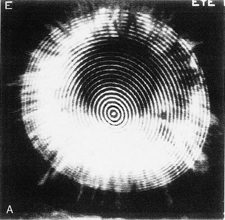 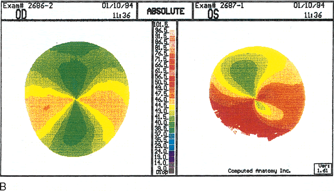 Fig. 12. Keratoglobus. A. Videokeratoscopic image of a patient with keratoglobus in the left eye
showing inferonasal narrowing of the rings, indicating steepening, but
without the pear-shaped configuration seen in pellucid marginal
degeneration. B. Videokeratography of the right eye shows marked against-the-rule
astigmatism of 6.3 diopters (D). C. The left eye shows irregular astigmatism with quite irregular power distribution. The
axis of lowest corneal power is shifted about 35 degrees
from the vertical axis, with a very asymmetric bow-tie configuration
and with the inferior low-power semimeridian positioned
above an area of high power at the inferior peripheral cornea. This
area of peripheral inferior corneal steepening extends to the steep oblique
semimeridians. (Karabatsas CH, Cook SD: Topographic analysis
in pellucid marginal degeneration and keratoglobus. Eye 10:451–455, 1996.)
Fig. 12. Keratoglobus. A. Videokeratoscopic image of a patient with keratoglobus in the left eye
showing inferonasal narrowing of the rings, indicating steepening, but
without the pear-shaped configuration seen in pellucid marginal
degeneration. B. Videokeratography of the right eye shows marked against-the-rule
astigmatism of 6.3 diopters (D). C. The left eye shows irregular astigmatism with quite irregular power distribution. The
axis of lowest corneal power is shifted about 35 degrees
from the vertical axis, with a very asymmetric bow-tie configuration
and with the inferior low-power semimeridian positioned
above an area of high power at the inferior peripheral cornea. This
area of peripheral inferior corneal steepening extends to the steep oblique
semimeridians. (Karabatsas CH, Cook SD: Topographic analysis
in pellucid marginal degeneration and keratoglobus. Eye 10:451–455, 1996.)
|
PERIPHERAL THINNING DISORDERS Terrien's Marginal Degeneration Terrien's marginal degeneration is a slowly progressive, painless
thinning of the corneal stroma of unknown etiology. It is typically bilateral
and is predominantly seen in men. Initially there is deposition
of refractile, yellow-white lipid deposits in the superior perilimbal
anterior stroma, with radial superficial vessels. Subsequently
a gutter 1- to 2-mm wide with intact epithelium develops. This
gutter runs parallel to, but does not involve, the limbus. Over
time there is deeper involvement of the stroma as well as progression
circumferentially. Complications include astigmatism and perforation.26 Mooren's Ulcer Mooren's ulcer is a rare form of peripheral ulcerative keratitis. In 30% of
cases it is bilateral. Although the pathogenesis is unknown, there
is a strong evidence that it is an autoimmune genetic disease, which
is supported by the findings of HLA class II DR17 and DQ2 in 83% of
cases; an inflammatory immune response; antibodies to
corneal antigens; and resolution with immunosuppressive therapy. It
is seen more commonly in Africa and India and is characterized by a previous
history of trauma, surgery or infection. The patient presents with
an acute, painful ulceration of the peripheral cornea that progresses
in a circumferential or transverse fashion. The borders of the ulcer
are overhanging; vessels extended from the limbus into the ulcer bed
without adjacent scleral melt.About 20% of the cases may progress
to perforation. Treatment includes local immunosuppression, systemic
immunosuppression, and/or removal of local stimulatory antigens such
as in lamellar conjunctivosclerokeratectomy.27,28 In these peripheral thinning disorders, flattening of the cornea occurs
in the affected meridian and steepening in the perpendicular meridian
due to biomechanical coupling. Characteristically there is high against-the-rule
astigmatism in a bow-tie pattern if the
process is confined to the superior and/or inferior periphery. As the
thinning progresses circumferentially to encompass the horizontal meridians, the
flat area extends and the perpendicular steep meridians
merge closer together, resulting in an arching bow-tie pattern. In
some cases, the central cornea remains relatively spherical, such
as with 360-degree peripheral thinning or, conversely, with a very
limited area of thinning (Fig. 13). These topography changes may not be specific but may be helpful
in the diagnosis and in the differentiation from other diseases.26–28 |
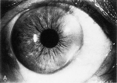  Fig. 13. Terrien's marginal degeneration. A. Slit lamp photograph showing peripheral corneal thinning in the inferior
and superior nasal quadrants of the right eye. Two areas with prominent
peripheral white lines were present from the 1- to 3-o'clock
and the 3:30- to 6-o'clock positions. A
small area of normal cornea separates the abnormal area from the limbus. B. Topographic map (normalized scale) demonstrates flattening of
the superior and inferior nasal peripheral cornea that corresponds to
the area of thinning. This flattening compromises the visual axis and
produces less than 1 diopter of cylinder, detected also by refraction
and keratometry. Wilson S, Lin D, Klyce S et al: Terrien's marginal
degeneration: Corneal topography. Refract Corneal Surg 6:15–20, 1990.)
Fig. 13. Terrien's marginal degeneration. A. Slit lamp photograph showing peripheral corneal thinning in the inferior
and superior nasal quadrants of the right eye. Two areas with prominent
peripheral white lines were present from the 1- to 3-o'clock
and the 3:30- to 6-o'clock positions. A
small area of normal cornea separates the abnormal area from the limbus. B. Topographic map (normalized scale) demonstrates flattening of
the superior and inferior nasal peripheral cornea that corresponds to
the area of thinning. This flattening compromises the visual axis and
produces less than 1 diopter of cylinder, detected also by refraction
and keratometry. Wilson S, Lin D, Klyce S et al: Terrien's marginal
degeneration: Corneal topography. Refract Corneal Surg 6:15–20, 1990.)
|
TYPES OF CORNEAL SURGERY Post-penetrating Keratoplasty The use of topography in the management of the cornea-transplanted
patient has facilitated visual rehabilitation. Topography can aid in: - Making decisions about trephination and graft size
- Identifying thin areas to be avoided in the graft-host junction
- Choosing a suturing technique
- Managing selective suture removal or adjustment
- Deciding on the need for a relaxing incision or a wedge resection in astigmatism
greater than 8 D
- Correcting refractive errors by a excimer laser procedureedit
- Postsurgical fitting of a contact lens29
Postoperative astigmatism is the major limiting factor for good vision
in patients with clear grafts. It has been reported that after penetrating
keratoplasty, 10% of the eyes have at least 5.00 D of keratometric
astigmatism. Studies have shown that the refractive power map
and axial power map correlate better with the manifest refractive cylinder
than tangential maps or keratometry. However, the axis of the astigmatism
is more accurate when measured by keratometry.30 Almost any topographical pattern may be seen post-keratoplasty. The
asymmetric bow tie was most commonly seen by many investigators, but
others have found the irregular pattern to be the most frequent.30–32 Several factors can affect corneal topography following surgery, including
the following: - Graft size (most surgeons oversize the donor button by 0.25 mm because
a difference of 0.5 mm may produce steepening, whereas a difference
of 0 mm may flatten the cornea)
- Depth of incision (lamellar vs. penetrating keratoplasty)
- Centration of trephination
- Preexisting astigmatism in the host and donor corneas
- Suture technique (interrupted vs. continuous, symmetry, and radiality; long
and deep bites may cause more compression and steepening, but
loose and superficial sutures produce wound gape and flattening
Corneal steepening is usually the result of a tight suture. Tight sutures result in local
flattening of the host-graft interface but a secondary steepening
of the central cornea. As a result of biomechanical coupling, there
is also flattening of the perpendicular meridian. Another cause may
be a vertical wound misalignment in which the central edge underrides
the peripheral edge. Tissue contraction due to cauterization or edema
of the wound edges may also lead to steepening. Corneal flattening is often due to a loose suture. It may also result from vertical wound
misalignment in which the central edge overrides the peripheral edge, too
superficial sutures that produces a posterior wound gape, or delay
in wound healing. Corneal irregular astigmatism may result when two nonperpendicular and nonadjacent sutures are tight, resulting
in steepness in two meridians. Non-radial suture bites
may also result in torsion and irregular astigmatism. Different suturing techniques have been used with the objective of decreasing
postoperative astigmatism. A single continuous running suture has
the advantage over interrupted sutures in that it may be adjusted intraoperatively
or postoperatively to redistribute corneal tension. The
suture is rotated from flat meridians toward steep meridians. Intraoperative
adjustment has been shown to be superior to postsurgical adjustment. Interrupted
sutures alone, or in combination with a continuous
suture, facilitate postoperative selective suture removal. Suture removal can decrease the refractive cylinder and improve visual
acuity. There is no universal protocol that establishes how many sutures
should be removed at one time, the interval between suture removals
or how many diopters of astigmatism would be improved. However, most
clinicians agree that if refractive astigmatism is less than 3 D and visual
acuity is acceptable, no sutures are removed. If this is not the
case then interrupted sutures can be removed as early as 3 weeks postoperatively
as long as there is a continuous suture in place. Interrupted
sutures are removed no earlier than 12 weeks if there is no continuous
suture in place. Usually one interrupted suture is removed in the
steep meridian (Fig. 14). The patient is then re-evaluated with topography and refraction
at 3 week intervals.
|
 Fig.
14. Irregular astigmatism in post-penetrating
keratoplasty produced by a tight suture at 165 degrees. (Courtesy
of Gregory Pamel, MD.) Fig.
14. Irregular astigmatism in post-penetrating
keratoplasty produced by a tight suture at 165 degrees. (Courtesy
of Gregory Pamel, MD.)
|
REFRACTIVE CORNEAL SURGERY Topography is relied on in refractive corneal surgery for screening diseases (contact
lens–induced corneal warpage, keratoconus), planning
surgery (incision location, length, and depth) and
in wavefront-guided LASIK. Postoperatively, corneal topography
changes can be quantified by difference maps, tangential (local) maps, and
indices such as the surface regularity index (SRI) and
theSAI. These tools allow the recognition of decentered
treatment zones, flap irregularities, and stromal ectasias. Topography
can also assist in calculation of intraocular lens power in postrefractive
surgery patients who are undergoing cataract surgery. Projection-based
systems are preferred because they do not require the anterior
corneal surface to be reflective and therefore can be used immediately
postoperatively. Cornea shape alteration can affect just the anterior surface or all the
layers of the cornea. In the former case, the superficial tissue is removed (excimer
laser, keratectomy), added (epikeratoplasty), or
structurally altered (laser thermokeratoplasty) without
alterations in the stroma or posterior cornea.34 In the latter case, the corneal stroma is changed either by incisions (radial
keratotomy, astigmatic keratotomy) or by applying persistent
mechanical forces (intrastromal corneal rings). Radial Keratotomy Radial keratotomy (RK) induces central flattening by deep radial
incisions. The central 3-mm optical zone remains untouched. The
corneal profiles seen after RK (Table 1) are oblate (79%) and a mixed pattern of oblate/prolate (18%). The radial incisions produce a rapid change
in slope called the paracentral knee (inflection zone) that lies between the zone of peripheral steepening
and central cornea flattening. Topographic patterns seen after
RK are the same spectrum as for normal corneas with the addition of
the polygonal pattern. The polygonal pattern is seen in 59% of
cases and is a concentric pattern with two or more angles (135 degrees) and
three or more nearly straight lines that correspond to
the central ends of the radial incisions. In all RK cases the corneal
asphericity is increased. Initially, maximal flattening is present at
the proximal end of the incisions in the paracentral zone, whereas the
central cornea remains steeper. With time, the central cornea becomes
flatter. The cornea can mimic a multifocal lens as a result of the
increased range of diopters within the pupillary aperture35 (Fig. 15). Table 1. Topographic Patterns Seen after RK Radial Keratotomy (RK) (From
Bogan et al.)
| Topography | | Normal (Bogan et al) (%) | RK (Bogan et al) (%) |
| Profile | Prolate | 100 | 3 |
| | Mixed (prolate/oblate) | 0 | 18 |
| | Oblate | 0 | 79 |
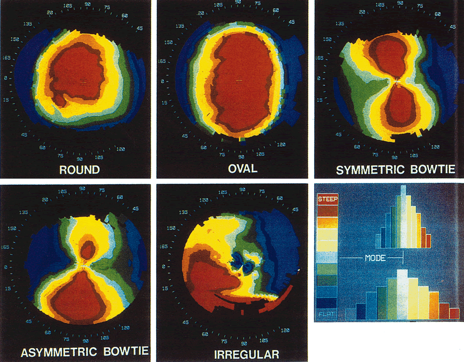
| Pattern | Round | 23 | 6 |
| | Oval | 21 | 0 |
| | Symmetric bow tie | 18 | 16 |
| | Asymmetric bow tie | 32 | 6 |
| | Irregular | 7 | 6 |
| | Polygonal | 0 | 63 | |
 Fig. 15. A polygonal pattern is seen in 59% of cases of radial keratectomy
incisions. (Courtesy of Gregory Pamel, MD.)
Fig. 15. A polygonal pattern is seen in 59% of cases of radial keratectomy
incisions. (Courtesy of Gregory Pamel, MD.)
|
Astigmatic Keratotomy Astigmatic keratotomy corrects astigmatism by flattening the steep meridian (with
paired relaxing corneal incisions) or steepening
the flat meridian (with wedge resection and/or compressive sutures). The
most common topographic patterns seen after astigmatic keratotomy
are symmetric bow tie and asymmetric bow tie.1 Intrastromal Corneal Rings Intrastromal corneal rings induce a steep peripheral ring and central corneal
flattening. The natural aspheric prolate shape is preserved1 (Fig. 16). |
 Fig. 16. Intrastromal corneal rings induce bilateral symmetric peripheral corneal
steepening and central flattening. (Orbscan, ORBTEK, Inc., Salt
Lake City, Utah.)
Fig. 16. Intrastromal corneal rings induce bilateral symmetric peripheral corneal
steepening and central flattening. (Orbscan, ORBTEK, Inc., Salt
Lake City, Utah.)
|
Photorefractive Keratectomy Photorefractive keratectomy (PRK) and LASIK correct refractive
error by reshaping the superficial corneal tissues. In LASIK, a corneal
flap of 120 to 190 μm is created using a microkeratome; the stromal
bed is then ablated using an excimer laser. At least 30% or 50 μm
of the stromal bed is left untouched in order to prevent iatrogenic
ectasia. Correction of myopia involves ablation of the central
cornea; topography after a successful procedure for myopia shows a well-centered
central corneal region of uniformly reduced corneal
power resembling an oblate configuration. There is a smooth power change
gradient with progressively decreasing power change proceeding from
the center to the periphery of the treatment zone. Topography after
successful treatment of hyperopia shows a larger-diameter treatment
zone in which the peripheral cornea has been concentrically ablated, producing
an exaggerated prolate pattern. Immediately after PRK, the topographic map shows the delineation of the
treatment zone. The most effective way to see the change produced by
PRK is by the use of a difference map. The difference between the preoperative
and postoperative map shows the profile of the ablation and the
uniformity of the laser beam. Preoperative corneas with a round or
oval (no astigmatism) pattern maintain this pattern after hyperopic
or myopic correction. Hyperopic astigmatics who have only sphere
correction do not have a change in their bow-tie pattern. However, in
myopic astigmatics who have only sphere correction, the red (steeper) bow-tie pattern becomes a blue (flatter) bow-tie
pattern in the perpendicular meridian. In astigmatic
correction, the preoperative red bow tie (where the oval ablation
zone was performed) becomes a blue bow tie in the same meridian. In general, the topography of post-LASIK eyes appears to change
very little after the first postoperative visit, unlike post-PRK
eyes (Fig. 17). Following the boom in refractive surgery procedures, a variety
of complications have been recognized. A visual acuity of 20/20 does not
necessarily correlate with a successful procedure. Subtle irregularities
in the cornea can result in complaints of glare, halos, decreased
contrast sensitivity, and polyopia. Topography assists in the recognition
of these irregularities. Several investigators have proposed various
classification schemes for the topography patterns seen following
LASIK with various excimer lasers.36–38 The topographical patterns seen after PRK are shown in Table 2.39–42 |
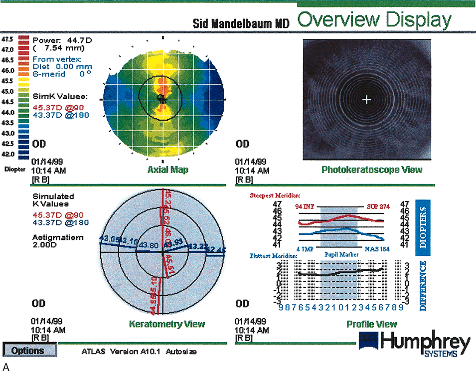 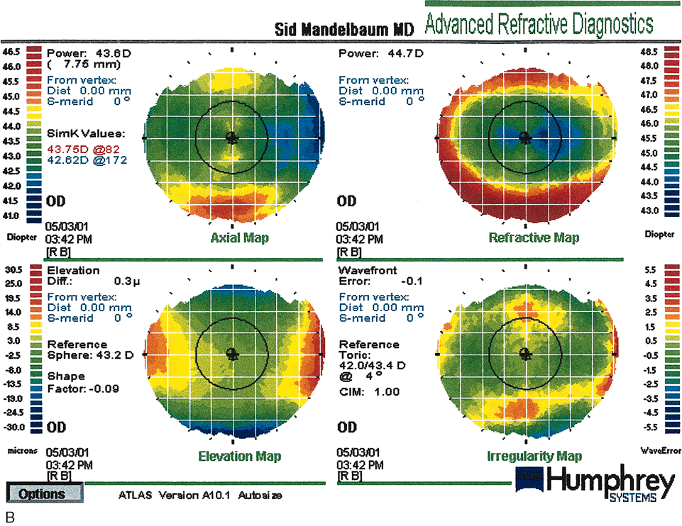 Fig. 17. Pre–photorefractive keratectomy (PRK) anterior elevation
map (A) topography compared with a post-PRK map (B). The circular central excimer laser treatment is demonstrated. There is
some residual with-the-rule astigmatism 28 months post-treatment. (Courtesy of Sid Mandelbaum, MD.)
Fig. 17. Pre–photorefractive keratectomy (PRK) anterior elevation
map (A) topography compared with a post-PRK map (B). The circular central excimer laser treatment is demonstrated. There is
some residual with-the-rule astigmatism 28 months post-treatment. (Courtesy of Sid Mandelbaum, MD.)
|
Table 2. Topographic Patterns After Photorefractive Keratotomy.
| Regular |
| Homogeneous | Uniform and symmetric flattening |
| Toric-with-axis | Bow-tie pattern with greater induced flattening in the steep preoperative
axis, resulting in a reduction of astigmatism |
| Toric-against-axis | Bow-tie pattern with greater induced flattening in the flat preoperative
axis, producing an increase in astigmatism |
| Irregular |
| Semicircular | Foreshortening of the ablation zone effect in one axis, 1.00 D less flattening
than the opposite axis, and >1.0 mm in sizea |
| Irregularly irregular | Generalized irregularities over the ablation zone defined as more of one
area >0.5 mm and >0.5 D, or one area >1.0 mm and 1.00 D not
corresponding to the other described patterns |
| Keyhole | Area of >1.0 mm and 1.00 D of less flattening extending in from the
periphery of the ablation zone |
| Central island | Central area of less flattening >1.0mm in size and >1.00D in power |
| Focal topographical varriants | Generally homogeneous pattern with irregularities, <1.0 mm and <1.00 D
in power |
D, diopter.
The two most common complications are central islands and decentration. Regardless
of classification schemes, most authors define a central island
as a central area of relatively less flattening. It measures at
least 1.0 mm in diameter and has at least 1.00 D greater power than the
surrounding cornea. It is surrounded 360 degrees by an area of greater
flattening and therefore does not extend into the periphery (Fig. 18). Central islands may occur as a result of reduced central ablation
or irregular healing. Reduced ablation may occur from uneven hydration
during ablation, with accumulation of fluid centrally, masking the
stroma. Delayed clearance of ablation debris may also mask the central
stroma. Cooler laser beams centrally may also cause a central island. Central
islands are associated with undercorrection, loss of best corrected
visual acuity, glare, monocular diplopia and halos. The highest
incidence is at 1 week postoperatively; at 1 year postoperatively, the
incidence is less than 2%. The resolution of central islands
is due to epithelial-subepithelial hyperplasia and corneal haze.43–48 |
 Fig. 18. A central island post-Lasik is a central area of relatively less
flattening. It measures at least 1.0 mm in diameter and has at least 1.00 diopter
greater power than the surrounding cornea. Central islands
may occur as a result of reduced central ablation or irregular healing. (Courtesy
of Gregory Pamel, MD.)
Fig. 18. A central island post-Lasik is a central area of relatively less
flattening. It measures at least 1.0 mm in diameter and has at least 1.00 diopter
greater power than the surrounding cornea. Central islands
may occur as a result of reduced central ablation or irregular healing. (Courtesy
of Gregory Pamel, MD.)
|
Decentration occurs most commonly as a result of patient movement secondary
to loss of fixation. Decentration is measured in relation to the
pupil center, rather than to the center of the cornea. Higher-order
refractive corrections have a greater incidence of decentration due, presumably, to
the longer treatment time. Decentration is considered
significant if it is greater than 0.5 mm, but its effect is modified
by the size of the pupil and the diameter of the ablation zone. Decentration
shows a similar pattern to that of asymmetric astigmatism (show
topography). This phenomenon produces visual effects (loss
of visual acuity, contrast sensitivity, glare, halos and polyopia) that
are greater in patients with large pupils and smaller treated
optical zones. Two types of eye-tracking systems have been
developed to prevent decentration during laser procedures. Postsurgical
centration can be demonstrated by using software that measures the
distance from the center of the pupil to the center of the treatment
zone and compares this with the corneal vertex, which is the center of
the cornea topography. Other complications that may be seen post-LASIK are debris or epithelial
cells under the flap, ectasia, striae, and flap defects resulting
in irregular astigmatism. Ectasia occurs as a result of changes in
the posterior corneal curvature (PCC). Iatrogenic keratoectasia
has been reported when the stromal bed is less than 250 μm after
LASIK. The average amount of ectasia induced under these conditions
is 13 μm. It is important to keep in mind that the error of the ORBSCAN
system in pachymetry measurement is ± 20 μm.34 CONTACT LENSES Contact lenses have been used to compensate for distortions of the anterior
corneal surface, leading to improved visual acuity. Computerized
videokeratoscopy systems contain software to assist the clinician in selecting
a lens that is most likely to fit a patient. These systems can
provide the clinician with initial lens parameters (posterior lens
curvature, optic zone diameter, overall lens diameter, and edge lift) and
a fluorescein-pattern simulation. The advantage is
that the patient has to try on fewer trial lenses before an appropriate
fit is found. In most cases, the clinician determines the final power
of the lens after trial lens insertion and over-refraction. Some
software programs will also provide the final power of the lens as
well. Corneal Warpage Contact lenses have been known to induce topographic changes in the cornea. This
phenomenon is known as corneal warpage and is generally reversible
with discontinuation of contact lens use. While warpage has been
documented with both rigid and soft lenses, polymethylmethacrylate (PMMA) and
rigid gas-permeable (RGP) lenses
have a greater mechanical effect on the cornea than soft lenses. Signs
of corneal warpage are keratometry mire distortion, significant changes
in keratometric measurements, and decreased spectacle visual acuity
in the absence of clinically observable corneal edema. Generally, RGP
lenses induce relative flattening of the cornea under the resting position
of the lens and may induce steepening peripherally beyond the lens
edge, producing an asymmetric oblate bow-tie pattern.49,50 Corneal warpage may simulate keratoconus with loss of central radial symmetry
and the presence of irregular astigmatism due to superior flattening
and inferior steepening. Lebow and Grohe compared topography indices
of keratoconics and corneal warpage subjects; they determined that
corneal shape factor, corneal irregularity measure, and corneal toricity
were greater in true keratoconics subjects.51 Refractive surgery candidates are required to discontinue use of contact
lenses for a period of time before ocular measurements are made in
order to resolve any changes induced by lenses. Corneal topography can
be used to diagnose warpage and to follow the resolution (Fig. 19). |
 Fig. 19. Corneal warpage secondary to soft contact lens wear. This case shows an
asymmetric oblate bow-tie pattern. Corneal warpage may simulate
keratoconus with loss of central radial symmetry and the presence of
irregular astigmatism due to superior flattening and inferior steepening. (Courtesy
of Gregory Pamel, MD.)
Fig. 19. Corneal warpage secondary to soft contact lens wear. This case shows an
asymmetric oblate bow-tie pattern. Corneal warpage may simulate
keratoconus with loss of central radial symmetry and the presence of
irregular astigmatism due to superior flattening and inferior steepening. (Courtesy
of Gregory Pamel, MD.)
|
Orthokeratology Orthokeratology intentionally manipulates the potential of RGP lenses to
modify anterior topography as a nonsurgical and variably reversible
means of improving vision in disorders such as myopia or keratoconus. The
technique involves fitting progressively flatter reverse-geometry
rigid contact lenses (lenses in which the secondary curvature
steepens) until the anterior corneal curvature has been altered
to the desired level of myopia reduction. Myopia reduction is modest, 1 to 2 D, and
is associated with central epithelial thinning and midperipheral
stromal thickening.52,53 |