|
| Chapter 23 Plain Roentgenographic Evaluation of Orbital Disease KEITH D. CARTER , JUNHEE LEE and JEFFREY A. NERAD Table Of Contents |
|
RADIOLOGIC PRINCIPLES STANDARD ORBITAL VIEWS RADIOLOGIC ORBITAL ANATOMY RADIOGRAPHIC CHANGES WITH ORBITAL PATHOLOGY REFERENCES |
| Patients with orbital disease or trauma represent a challenge to the clinician. The clinical evaluation may provide useful information, but the interior of the orbit, unlike the eye, cannot be observed directly. This limitation in the clinical evaluation often necessitates radiologic studies to aid in diagnosis and allow for appropriate management. Plain x-ray films can delineate bony detail of the orbit and face, along with moderate soft tissue changes. The incidence of definitive positive findings with plain film evaluation of orbit diseases ranges from 10% to 42%.1, 2, 3, 4 The improved resolution of bone and soft tissue seen with newer techniques of computed tomography (CT) and magnetic resonance imaging has decreased the use of plain x-ray studies. In most cases of orbital disease, CT or magnetic resonance imaging is required to complete the evaluation. However, plain film studies continue to provide useful information, especially when used as a screening tool. This chapter demonstrates how plain films may be useful and complement the use of newer imaging techniques. |
| RADIOLOGIC PRINCIPLES | |
Because the orbit is in such close proximity to the larger bones of the
skull, multiple shadows overlap one another and obscure some radiographic
details. Numerous radiologic projections have been developed to evaluate
the bony structures of the orbit and face.5,6 These various projections attempt to eliminate some of the obvious overlapping
shadows and allow for better detail of the bony orbit. For maximal
image clarity, the distance from the object to the x-ray cassette
should be minimized and the distance between the subject and the x-ray
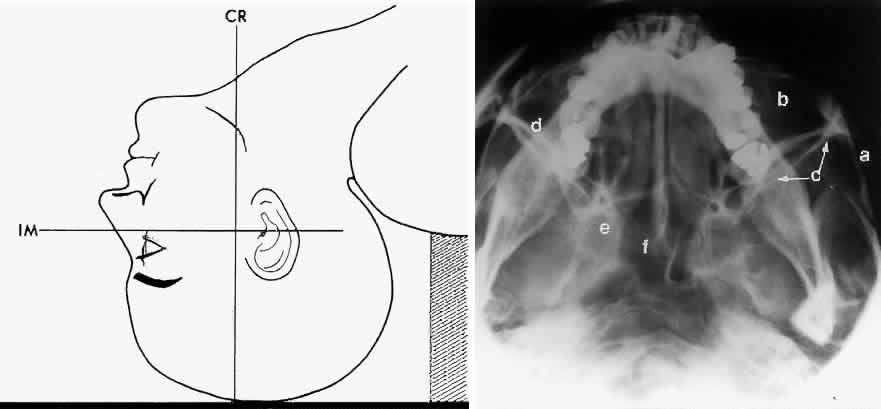
beam maximized. This principle is demonstrated in Figure 1.
|
| STANDARD ORBITAL VIEWS | |||||
| A standard radiographic study of the orbit and paranasal sinuses consists
of the following views: Waters projection, Caldwell projection, lateral
projection, and basal projection (submento-vertex). Oblique apical
projections of the optic canals are additional views available if there
is clinical evidence of posterior orbital pathology, such as traumatic
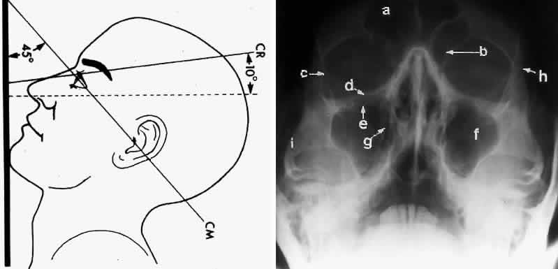
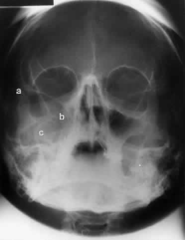
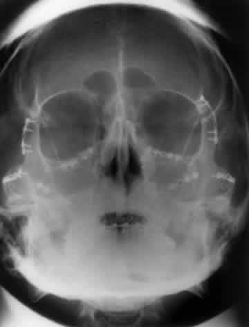
optic neuropathy or an optic nerve tumor. WATERS PROJECTION In an attempt to improve the visualization of the maxillary and ethmoid sinuses, in 1915 Waters and Waldron7 described a radiographic projection (Fig. 2) that eliminated the overlapping shadows of the dense petrous ridge of the temporal bone. Waters projection is created by placing the chin of the patient on the x-ray cassette with the canthomeatal line (the line that connects the lateral canthus and the external auditory meatus) at 37 degrees to 45 degrees.5,6 This orientation is accomplished if the nose of the patient is approximately 0.5 to 1.5 cm above the x-ray plate.7,8 A mnemonic is—the patient raises the chin up to sip water.
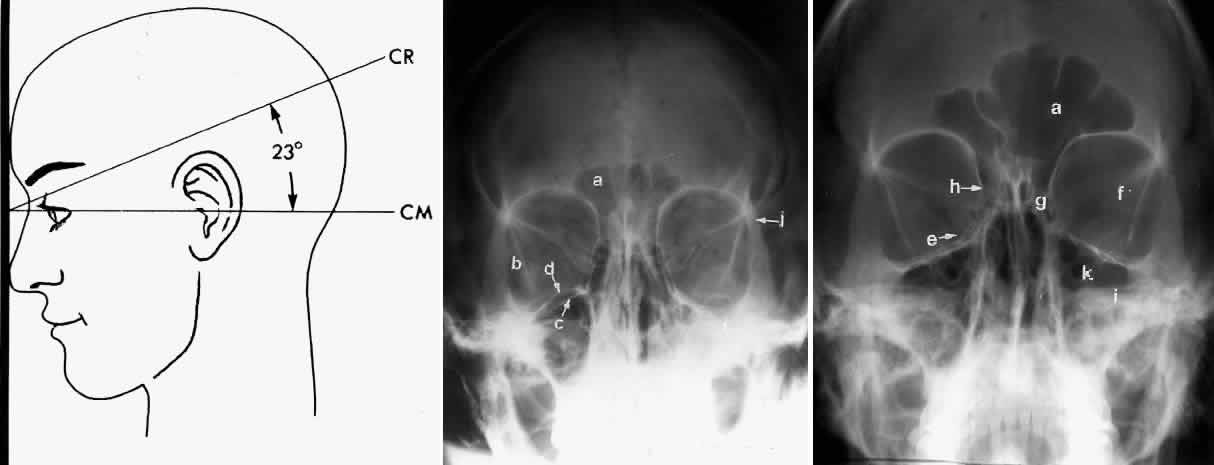
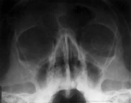
Waters view provides the best image of the maxillary antrum and good images of the orbital rim, orbital floor, zygomatic bones and arches, lesser wing of the sphenoid, and infraorbital foramen. This view is useful to the clinician in orbital floor fracture assessment because of the clear image of the orbital floor and the underlying maxillary sinus. The floor of the orbit should form a continuous radiographic line with the lateral wall of the orbit. Confusion can occur regarding the location of the orbital floor and its relationship to the orbital rim. The orbital floor is located inferior to the orbital rim not in the same plane, because of the orientation of the patient's head in Waters projection. A soft tissue density in the roof of the maxillary sinus or opacification of the floor of the sinus suggests an orbital floor disruption. CALDWELL PROJECTION In 1918 the evaluation of the frontal and ethmoid sinuses prompted Caldwell9 to describe a projection (Fig. 3) that eliminates the superimposition of the sphenoid bone on these paranasal sinuses. The patient is positioned with both the nose and forehead against the x-ray cassette while the x-ray beam is directed downward 15 degrees to 23 degrees to the canthomeatal line.5,6,9 This orientation also projects the petrous bones inferior to the orbit, thus avoiding obscuration of the orbital structures. As in the Waters view, the Caldwell view is a posterior-anterior projection. This excellent view of the frontal and ethmoid sinuses also allows good visualization of the orbital rims, greater and lesser sphenoid wings, lacrimal gland fossa, medial orbital wall, and both the superior and inferior orbital fissures.10 The innominate line is prominent in this view and represents the depression on the temporal surface of the greater wing of the sphenoid bone where it forms the medial wall of the temporal fossa or lateral wall of the orbit. This innominate line can be straight, end with a medial right angle turn, or continue inferiorly to form the outline of the pterygoid plate.8 A lack of continuity of the innominate line suggests a fracture of the lateral orbital wall.
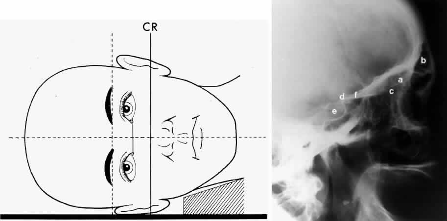
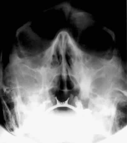
LATERAL PROJECTION Lateral projection (Fig. 4) is created by placing the patient's head against the x-ray cassette and centering the cassette on the lateral canthus. The x-ray beam is directed perpendicularly to the midpoint of the cassette and enters the patient's head at the lateral canthus remote from the cassette.5,6 This projection provides a view of the sagittal plane of the skull. Because of the overlapping skeletal structures, interpretation of unilateral disease processes is difficult. The structures that can be identified and best evaluated include the sphenoid, frontal, ethmoid, and maxillary sinuses. This lateral view also shows the sella turcica, the anterior and posterior clinoid processes, the nasopharynx, and the cribriform plate. The orbital structure best evaluated is the orbital roof. The floor of the orbit is visible but evaluation is difficult because of the upward slope, from lateral to medial, toward the orbital apex. This slope causes the floor to appear at different levels on the lateral view.11 The lateral projection, although not as useful as the frontal projections, gives information concerning air-fluid levels in traumatized patients, when only a horizontal projection is possible.
BASAL PROJECTION (SUBMENTO-VERTEX) The basal projection (Fig. 5) for the evaluation of the sphenoid sinus and skull base was described initially by Arthur Schuller12 in 1905 and later popularized in this country by Bowen.13 This projection is obtained with the patient's neck extended either in the supine or upright position. The top of the head is placed so that the infraorbitomeatal line is parallel with the x-ray cassette. The x-ray beam is directed at right angles to the infraorbitomeatal line.5,6 This view shows the lateral walls of the orbit and maxillary sinuses well. The nasopharynx, pterygoid plates, pterygopalatine fossa, and the sphenoid and ethmoid sinuses may also be inspected. Because of the extreme head position, any history of a neck injury is a contraindication to this radiologic study.
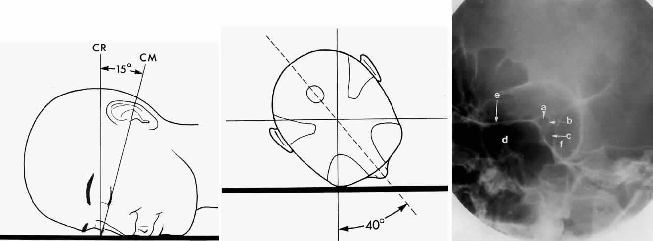
OPTIC FORAMEN (RHESE POSITION) In 1911 Rhese14 described a projection (Fig. 6) for the evaluation of the ethmoid sinuses and the optic foramen. The patient is positioned with the orbit to be studied against the x-ray cassette. The zygoma, nose, and chin should touch the cassette. The x-ray beam is directed posterior-anteriorly at 40 degrees to the midsagittal plane.5,6 In this position the optic canal is in the inferolateral quadrant of the orbit and oriented perpendicular to the x-ray cassette.15 Variations of this standard position can be used to view other structures of interest. The Rhese projection allows assessment of the orbital apex, in particular, the optic foramen, optic strut, and the upper ethmoid sinus. A pneumatized anterior clinoid process may simulate the optic foramen. The landmark for finding the foramen is to find the planum sphenoidale; the optic foramen lies at its lateral end. The optic canal may be evaluated for expansion or compression by disease processes, such as optic nerve tumors (glioma and meningioma) and trauma. CT and magnetic resonance imaging show much better detail and therefore have replaced the use of plain films for evaluation of the optic canal.
|
| RADIOLOGIC ORBITAL ANATOMY | |||
| Plain film studies provide excellent images of the bony structures of the
orbit and face. The orbit consists of seven bones: frontal, sphenoid, zygomatic, maxillary, lacrimal, ethmoid, and palatine. The orbit is
pyramidal in shape, widest anteriorly and narrowing posteriorly. Whitnall
described the orbit as a quadrilateral pyramid with its base directed
forward, outward, and slightly downward.16 A description of the bones that make up these orbital walls serves as
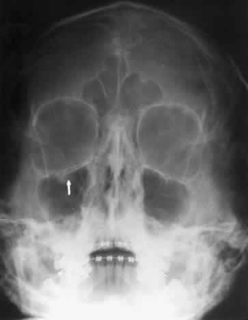
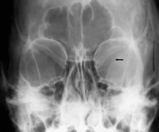
a guide to the radiologic evaluation of the orbit. The orbital rim is a distinct radiopaque structure on any frontal radiographic study. The shape of the adult orbital rim is rectangular, being slightly wider horizontally (40 mm) than vertically17 (35 mm). The superior portion of the rim is made of the frontal bone. This section of the rim is sharp in females but becomes more rounded and prominent with frontal sinus development in males.18 The medial rim is anteriorly formed by the frontal process of the maxilla and the maxillary process of the frontal bone. The frontal process of the zygomatic bone and the zygomatic process of the frontal bone comprise the lateral rim. The inferior orbital rim is formed medially by the maxilla and laterally by the zygomatic bone. The orbital roof consists mainly of the orbital plate of the frontal bone. The lesser wing of the sphenoid contributes a small portion to the posterior aspect of the roof. The roof is concave in shape and varies in thickness. The fossa for the lacrimal gland is located anterolaterally. The lateral projection gives the best view of the roof. One can usually make out each orbital roof on this view. Pathology involving the frontal sinus, which is located between the orbits anteriorly, can involve the roof of the orbit and even cause bone displacement of the eye. The roof is seldom involved in orbital trauma. The orbital floor consists of the maxillary, zygomatic, and palatine bones. The floor is thinnest medial to the infraorbital canal, which is the location of most orbital floor fractures (Fig. 7). As mentioned earlier, the floor slopes upward from the lateral to the medial wall. The floor extends toward the orbital apex but does not reach the apex. This orientation of the floor makes frontal projections more informative than the lateral projection.
Waters view gives the best image of the anterior and middle portion of the floor. This is possible because extension of the neck brings the floor into a position that is tangential to the x-ray beam. The floor is represented by the most inferior radiopaque line, whereas the orbital rim will be the line above it.10 The vertical distance between these lines should be approximately 1 cm.19 This relationship between the floor and the orbital rim should be symmetric between the two orbits. Any asymmetry should suggest a fracture of the orbital rim or floor. The Caldwell view of the floor gives the best information concerning the posterior orbital floor. Again, this is because the posterior floor is more tangential to the x-ray beam than the more anterior orbital floor. Evaluation of the orbital rim may be limited by superimposition of the rim on the orbital floor or petrous bones. This projection can cause confusion because the floor is evaluated from anterior to posterior. The floor projects below the rim anteriorly, about equal with the rim at the midorbit, and superior to the rim in the posterior orbit.10 The orbital floor and underlying maxillary sinus can be adequately evaluated by using both the Waters and Caldwell views. The anterior aspect of the lateral orbital wall is formed by the zygomatic process of the frontal bone and the orbital process of the zygomatic bone. The posterior portion of the wall consists of the greater wing of the sphenoid bone. The lateral orbital wall is thick and runs at an angle of 45 degrees to the midline of the face. This orientation of the lateral wall lessens the radiographic information obtained in the lateral or frontal views of the orbit. The entire lateral wall is best viewed with a submento-vertex projection, in which the x-ray projection is tangential to the lateral wall. In this projection the lateral wall may be confused with the posterior wall of the maxillary sinus. The lateral wall of the orbit should course straight toward the orbital apex. The posterior wall of the maxillary sinus will have an S-shaped configuration that begins at the zygomatic arch, extends into the lateral wall, and then turns anteriorly to become the medial wall of the maxillary sinus. The posterior segment of the lateral wall courses posterior medially and can be seen in anterior projections such as the Caldwell view. This view allows direct visualization of the greater sphenoid wing contribution to the lateral wall. Bone density changes in the greater wing of the sphenoid, such as from a meningioma, can be detected. Fractures of the lateral orbital wall can occur from blunt trauma to the malar prominence. The zygomatic complex fracture (tripod) results from separation of the zygomatic-frontal, zygomatic-temporal, and the zygomatic-maxillary sutures. These fractures are associated with an inferior displacement of the malar prominence and a rounded lateral canthus (Figs. 8 and 9).
The medial orbital wall consists of the frontal process of the maxilla, the lacrimal bone, and the lamina papyracea of the ethmoid bone and runs parallel to the sagittal plane. The Caldwell projection provides a detailed image of the posterior medial orbital wall. This wall is thin but the air cells of the ethmoid sinus provide a clear contrast, and, therefore, a distinct image of the posterior portion can be achieved. These air cells hinder the evaluation of the more anterior medial wall because of superimposition. Opacification of the ethmoid sinus, as in ethmoid sinusitis, prevents reliable assessment of the bony detail of this wall because of loss of contrast. Waters projection gives the best information on the anterior medial wall because of the more superior location of the anterior structures, whereas the posterior wall is obscured by the overlying nasal bones. The superior orbital fissure is bordered by the greater wing of the sphenoid below and the lesser wing above. Medial to the superior orbital fissure is the optic strut that separates the fissure from the optic canal. The superior fissure is oblique, whereas the inferior fissure has a vertical orientation. There is considerable variation in the size and shape of this fissure.20 The superior orbital fissure is best seen on the Caldwell projection. The inferior orbital fissure lies in the floor of the orbit and can also be seen in the Caldwell projection. |
| RADIOGRAPHIC CHANGES WITH ORBITAL PATHOLOGY | ||||||||||||||||||||||||||||||||||||||||||||||||||||||||||
| Orbital emphysema may result from disruption of an orbital wall that is adjacent to the
paranasal sinuses. The detection of air in the orbit is increased if the
patient's radiologic studies are performed in the upright position. Orbital
emphysema may be seen in 45% of cases of medial wall fractures
and 35% of floor fractures.21 Loss of vision can occur if this air is forced into the orbit because
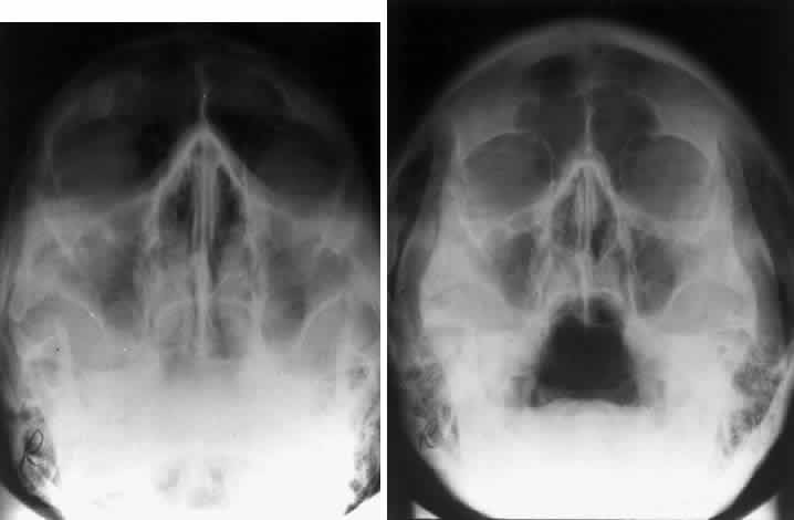
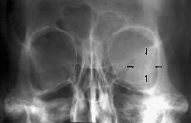
of sneezing or vomiting and is unable to escape.22 Calcification in the orbit can be seen in retinoblastoma, meningioma, organized hematoma, or a phlebolith associated with venous malformations. Intraocular calcification is seen with tumors such as retinoblastoma or with degenerative changes of the lens, choroid, or vitreous23 (Figs. 10 and 11).
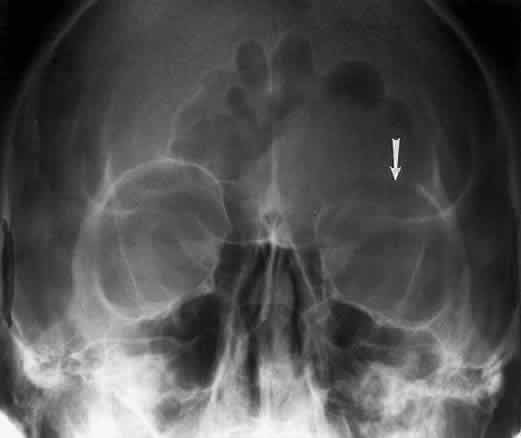
Bony destruction usually results from a rapidly growing process such as a tumor of the lacrimal gland or paranasal sinuses (Fig. 12). Sinusitis or a mucocele can also cause bone destruction or dehiscence of the orbital bones. Mucoceles most often originate in the frontal and ethmoid sinuses, and destruction of bone is noted radiographically in 70% of cases24 (Fig. 13). Encephaloceles may also cause a disruption in the orbital bones, usually superomedially. Neurofibromatosis is associated with dysplasia that can involve large segments of the greater wing of the sphenoid. Pulsating exophthalmos may be a clinical finding.
Hyperostosis of the orbital bones may be associated with a variety of disorders. The most common cause is a meningioma of the sphenoid bone (Fig. 14). Fibrous dysplasia, osteoblastic metastatic disease, or Paget's disease can also cause these bony changes.
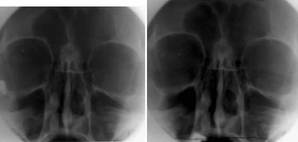
The orbital dimensions—orbital margin, superior orbital fissure, optic foramen—should be symmetric in size and shape. Mild asymmetry may be normal, but marked asymmetry should alert the clinician to search for pathologic causes. The vertical dimension of the orbit is best measured in the frontal plane with a nose-chin view as described by Lloyd.25 A difference of 2 mm or more is considered abnormal. The orbital dimensions can increase with any long-standing mass lesion that raises the intraorbital pressure. Lesions outside the muscle cone are more likely to cause localized enlargement, whereas intraconal lesions lead to a generalized orbital expansion. Such lesions include hemangiomas, optic nerve gliomas, meningiomas, and congenital glaucoma with buphthalmos or microphthalmos with cyst. Smaller orbits may be due to microphthalmos, enucleation in childhood, or congenital facial disorders. The superior orbital fissure has interpersonal and intrapersonal variations. The fissure should be symmetric, but there is no good measurement that identifies pathology, other than marked asymmetry. The fissure can be enlarged by infraclinoid aneurysm, carotid-cavernous fistulas, pituitary tumors, and meningiomas.26 Less common causes for enlargement include hemangiomas, lymphoma, mucocele of the sphenoid sinus, and neurofibromatosis (Fig. 15).
The optic foramen should measure 6 mm vertically and 5 mm horizontally. Asymmetry greater than 1 mm or a vertical dimension greater than 6.5 mm is considered abnormal.15,27 Ninety-eight percent of patients have optic canals that vary by less than 1 mm.27 Concentric enlargement of the foramen and optic canal can be seen with optic nerve gliomas, meningiomas, neurofibromatosis, and less commonly an aneurysm of the ophthalmic artery (Fig. 16). A decrease in the optic foramen and canal dimension can be seen in fibrous dysplasia, Paget's disease, hyperostosis secondary to a meningioma, or microphthalmos (Fig. 17, Table 1).
Table 1. Summary of Radiographic Projections and Structures
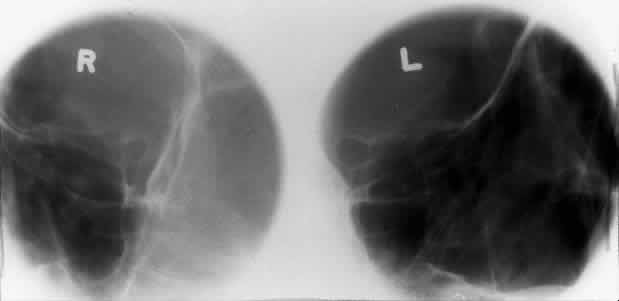
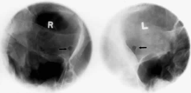
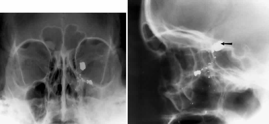
CT imaging has largely replaced plain radiography as the appropriate imaging modality for orbital fractures, but in situations in which CT is not possible, plain films remain useful. Caldwell and Waters projections are standard views to evaluate the orbital floor and medial wall. The reported sensitivity of plain radiography for orbital fractures were 71% to 89% for medial wall fractures and 73% to 86% for orbital floor fractures.28,29 Furthermore, according to at least one study,29 medial wall and orbital floor fractures missed by plain radiographs are generally small, nondisplaced, and clinically insignificant. Foreign bodies of the eye or orbit can be detected with plain films. Although standard radiography should theoretically be able to visualize metallic fragments as small as 0.1 mm by 0.1 mm by 0.1 mm,30 a 1991 retrospective study reported lower actual sensitivities: In patients with a high clinical suspicion for an orbital or ocular foreign body, plain radiographs showed a 90% sensitivity for metallic foreign bodies, 71% sensitivity for glass, and lower sensitivities for wood and other materials. Metallic foreign bodies in the cornea showed a particularly high false-negative rate.30,31 CT is now generally regarded as the imaging method of choice to identify suspected foreign bodies in the globe or orbit. A laboratory study comparing plain radiography with CT demonstrated that plain films clearly visualized iron, graphite, and glass (containing trace lead) but could not distinguish between the three. CT, on the other hand, not only was able to distinguish between iron, graphite, and glass but was significantly more sensitive to wood and plastic.32 The localization of foreign bodies with plain films is a recurring challenge. Echography and CT have diminished the need for plain film techniques for localization of foreign bodies, but the latter can be used when other imaging modalities are unavailable. Frontal and lateral projections are standard views in these studies (Fig. 18). Localization of a foreign body within the globe is possible with bone-free examination using dental film or by ocular rotation. This latter study localizes the foreign body to either the anterior or posterior segment of the eye. If the foreign body is anterior, the object will rotate in the same direction as the eye. The object will move in an opposite direction to eye movement if its location is in the posterior segment of the eye33 (Fig. 19). Pfeiffer34 and Worst35 used contact lenses as reference devices in localizing foreign bodies. These techniques are less commonly used.
In 1986 Kelly and colleagues reported a case of unilateral blindness caused by movement of an intraocular foreign body as the patient was removed from a magnetic resonance (MR) imager.36 Subsequently, any patient with possible intraorbital orintraocular metallic foreign bodies underwent plain film screening before MR imaging. Studies that illustrated the unreliability of patient histories regarding foreign bodies supported plain film screening of any patients with occupational risk, with or without a history of penetrating trauma.37,38 However, in light of reports suggesting a very low risk of metal fragment movement during MR, some controversy exists about this level of stringency.30,36 Cost-effectiveness analyses argue that simple occupational history alone does not justify screening radiographs and that only those patients with a history of foreign body or penetrating injury warrant screening radiographs.39,40 |