Chapter 108
Diagnostic Ophthalmic Ultrasonography
YALE L. FISHER, FABIO NOGUEIRA and DANIELLE SALLES
Main Menu   Table Of Contents

Search

BASIC PRINCIPLES
EXAMINATION TECHNIQUES
CLINICAL APPLICATIONS
3D TOMOGRAPHIC ULTRASONOGRAPHY
PRESERVATION AND DOCUMENTATION
REFERENCES

Developed in the late 1950s and early 1960s,1–5 diagnostic ophthalmic ultrasonography remains a critical ancillary test for clinical evaluation of the opaque media globe and abnormal orbit. In clear media, its capabilities for tissue characterization have made it extremely useful for intraocular and orbital tumor identification, especially when coupled with clinical, radiographic, and magnetic imaging information. Real-time, kinetic ultrasound technique and improved image quality also permit hyaloid positional evaluation of clear vitreous. Further, recent computer advances have made possible tomographic three-dimensional (3D) ultrasonic imaging of the anterior and posterior segment.
Back to Top
BASIC PRINCIPLES
Ultrasound is an acoustic wave with a frequency greater than 20 kHz. The frequencies used in diagnostic ophthalmic ultrasonography are 8 to 25 MHz for imaging the posterior segment of the eye and orbit and 50 MHz for imaging the anterior segment.

Clinical diagnostic forms of ultrasound are based on physical principles of pulse-echo technology and tissue acoustic impedance mismatch. Pulse-echo technology employs synthetic crystal transducers to produce ultrasonic wavefront pulses and retrieve echoes for electronic display and processing. Send-receive sequences are repeated thousands of times each second.

Echoes are generated at adjoining tissue interfaces that display differences in acoustic impedance: the greater the difference, the stronger the echo. Retinal tissue, for example, is sonically much different than vitreous (which is essentially water). Therefore, strong reflections occur at such interfaces. When adjoining tissues have relatively small differences in acoustic impedance, as with mild vitreous hemorrhages or clumped intravitreal cells, small or weak reflections are seen.

Similar interpretation principles are useful in evaluating types of ocular and orbital tumor tissue. Some lesions demonstrate low-amplitude internal reflectivity; few echoes are seen, and such lesions are described as ultrasonically homogeneous. In contrast, others demonstrate high-amplitude internal reflections; multiple strong retinal echoes are seen, and these lesions are described as ultrasonically heterogeneous. Either tissue type may in addition shadow deeper structures by absorbing or reflecting sonic energy. The presence or degree of shadowing often aids interpretation of ocular and orbital lesions by demonstrating sonic attenuation.

Once reflected, echoes are received, amplified, and electronically processed. They are displayed in visual format as A-scan or B-scan images. A-scan (A-mode or time-amplitude) ultrasonography is used predominantly for tissue characterization and interpretation. The horizontal axis of this display represents time or distance and is useful for linear measurements, whereas the vertical dimension reveals echo amplitude and is useful for characterizing tissues (Fig. 1). A-scan may be performed independently of B-scan. B-scan (B-mode or intensity-modulated) ultrasonography provides a cross-sectional image of the globe and orbit (Fig. 2). B-scans are used predominantly for topographic information. There are overlaps of information from A-scan and B-scan; most physicians rely on both forms for adequate ultrasound interpretation, and instruments are available that present B-scan and A-scan images simultaneously (Fig. 3). The display images are presented horizontally in contact scanning and vertically with waterbath (immersion) scanning6–8 (Fig. 4).

Fig. 1. A-scan time amplitude ultrasonogram. The horizontal axis represents time or distance. The vertical deflections represent echo amplitude.

Fig. 2. Contact B-scan. Cross-sections are presented horizontally. Normal globe, anteroposterior view with lens capsule seen toward the left of the display, optic nerve and orbital fat behind the globe seen toward the right.

Fig. 3. Contact B-scan and simultaneous A-scan with visible steerable vector line (white) demonstrate the source and position of the A-scan display seen at the bottom of the display screen. Anteroposterior view with optic nerve seen toward the top right of the display.

Fig. 4. Immersion B-scan. B. Simultaneous A-scan, vertical format. Cornea and anterior segment are seen easily with waterbath stand-off. A-scan is imaged separately to the side. (Courtesy of DJ Coleman, MD, and Sue Woods, ultrasound laboratory, New York Hospital.)

Back to Top
EXAMINATION TECHNIQUES
The techniques developed for clinical examination have remained essentially unchanged for the past 20 years.9 A formal examination technique is used for architectural evaluation and tissue characterization.

The B-scan image, a two-dimensional crosssectional display of the globe and orbit, is more easily interpreted than A-scan, especially by examiners familiar with interpretation of ophthalmic pathology, where microscopic and gross crosssectional evaluation of the globe and orbit are routine and often topographically similar to B-scan cross-sections.

Several concepts are critical to accurate interpretation of B-scans. These concepts, although relatively easy to define, require considerable experience before the examiner feels comfortable with diagnosis in opaque media situations. These concepts are real time, gray scale, and threedimensional thinking.

Real time refers to the display of motion or movement during B-scan imaging. This capability is one of the greatest advantages of B-scan. Differences in mobility of a variety of movable intraocular abnormalities can be easily detected. For example, the rapid movement of vitreous hemorrhage is usually easy to appreciate and differentiate from the slower, undulating movements of a recent, rhegmatogenous retinal detachment. On occasion, movement of intraocular structures can be used for detecting abnormalities that lie immediately behind vitreous opacification and may be seen only when the vitreous opacities are moved away from the ocular wall, set in motion by command voluntary movements of the patient's globe (Fig. 5). Gray scale refers to the variable gray tone of display screen echoes. Strong returning signals (echoes) appear white, whereas weaker reflections are seen as gray, the shade depending on echo strength. Examples of strong reflectors of sound include retinal tissue, sclera, and calcifications of any type (Fig. 6). Weaker echoes from clotted or clumped cells within the vitreous are usually easy to differentiate from the stronger reflectors of sound (Fig. 7). Grading of echo strength may be performed only when the examining ultrasound beam is perpendicular to the object of interest, ensuring the strongest possible reflections. However, in the world of ultrasound interpretation, there are many exception to the rules. Tissues that are usually mild reflectors of sound, such as hemorrhage, can at times appear quite strong, especially in complex or multiple pattern disorders, as frequently occur in severe ocular trauma. These apparent inconsistencies often cause misinterpretation by the novice. With experience obtained by multiple examinations, careful follow-up, and clinical correlation whenever possible, diagnostic acumen rapidly improves.

Fig. 5. Contact B-scans. A. Heavy formed vitreous hemorrhage obscuring choroidal mass. B. Voluntary movement of the globe causes the formed vitreous to shift, permitting easy detection of the ocular wall mass.

Fig. 6. Contact B-scan. Calcified drusen of the optic nerve head create strong reflections in B-scan imaging because of their high acoustic impedance mismatch with surrounding structures. B. Contact B-scan and simultaneous A-scan: asteroid hyalosis. Characteristic high reflectivity of vitreous calcium soaps is easy to appreciate in B- and A-scans.

Fig. 7. Contact B-scan. Clotted or clumped cells, such as those seen in mild vitreous hemorrhage, appear pale gray.

3D thinking is the third B-scan concept necessary for accurate interpretation, and the most difficult to master. During B-scan examinations, the contact probe is almost always in motion, creating multiple, ever-changing two-dimensional B-scan cross-sections that must be mentally combined to create a 3D image of the globe and orbit. This technique is most easily mastered by those familiar with 3D spatial relations. The recent development of tomographic ultrasonography makes this concept easier to master because the student can use the computerized 3D image repeatedly, creating a wide variety of theoretical tomographic slices from the 3D image. Recognition of these patterns during future examinations becomes easier.

During contact B-scan imaging, each quadrant of the globe is scanned systematically from probe positions that avoid, if possible, any passage of the examining or returning sound through the artifact-inducing lens system (Fig. 8). For the beginner, practice with clear media patients, such as those with total or partial retinal detachment, is essential (Fig. 9). The ultrasonically derived vitreoretinal drawing can then be compared to standard optical examinations. As experience increases, similar but more difficult cases can be attempted. Specifically, B-scan examination of diabetic patients with traction retinal detachments and clear media should be attempted and compared to visually controlled drawings. These self-testing exercises, especially in complex cases, provide the examiner a feeling for his or her level of competence and reliability in 3D thinking. Opaque media cases can then be approached with greater confidence and diagnostic accuracy.

Fig. 8. Contact ultrasound probe positions are chosen to avoid passage of the examining beam or returning echoes through the artifact-inducing lens system.

Fig. 9. Contact B-scan: total retinal detachment, anteroposterior view. Characteristic V-shaped appearance with attachment to the optic nerve head.

Back to Top
CLINICAL APPLICATIONS
We prefer simultaneous B-scan and A-scan imaging, relying on both B-scan gray scale and A-scan amplitude interpretation for ultrasound tissue 
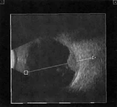
characterization. Tumor height is usually calculated from A-scan images; this is an important measurement for initial and follow-up examination.10

TUMORS

A-scan tumor characterization is often extremely helpful to the clinician. A thorough understanding of ophthalmic pathology is critical to interpretation and often predictive of typical A-scan tumor patterns.

Choroidal malignant melanoma, perhaps the most widely studied intraocular mass lesion, has the most reproducible and reliable A-scan pattern. Usually, the initial echo seen in A-scan is a high-amplitude spike secondary to the strong vitreoretinal surface echo overlying the tumor mass. Once the examining sonic beam has passed into the tumor tissue, a rapidly declining amplitude cadence is noted, a consequence of increasing ultrasonic tissue homogeneity. Clinical knowledge of the typical microscopic tumor pattern of tightly packed, homogeneous small cells makes 
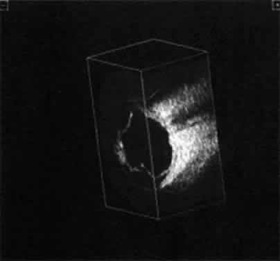
anticipation of relatively low reflectivity possible (Fig. 10). This same low-amplitude reflectivity in B-scan imaging produces a picture that makes the melanoma mass appear hollow. Often, tumor-infiltrated choroid also appears dark (Fig. 11). This change in the normally highly reflective choroidal tissue is widely but inaccurately called choroidal excavation. The terms “hollowing” and “choroidal excavation” are misleading because these tumors are not hollow and the choroid is not excavated. Nevertheless, these terms have been used so frequently in past literature 
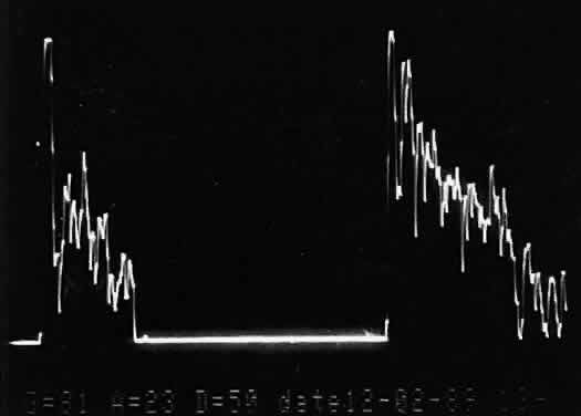
that any change in vocabulary is unlikely.

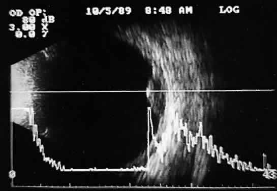
Fig. 10. Contact B-scan and simultaneous A-scan: choroidal malignant melanoma. Note the strong initial echo from the overlying retinal tissue, followed by a rapid decline in A-scan echo amplitude within the deeper tumor tissue, a consequence of increasingly homogeneous tissue. High reflectivity is again seen at the level of the sclera and orbit.

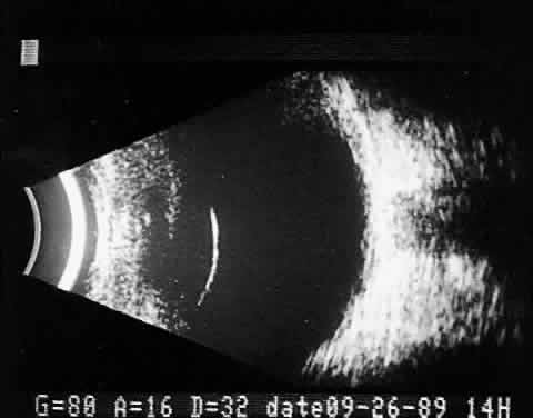
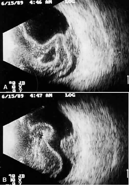
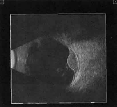
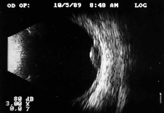
Fig. 11. Contact B-scan: malignant melanoma, demonstrating hollowing and choroidal excavation.

Tumors with great acoustic heterogeneity, such as choroidal hemangiomas, where adjoining cell and tissue layers have marked differences in acoustic impedance, create large echo amplitudes at each interface. These tumor types have typical high internal reflections at each major interface. These high internal reflections make the lesions appear solid white in B-scan displays and produce highamplitude spikes during A-scan
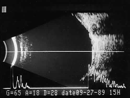
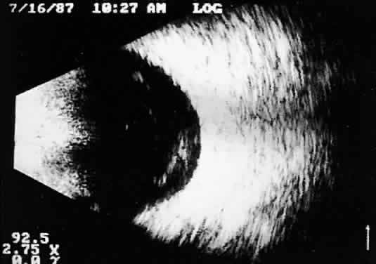
 imaging (Fig. 12).

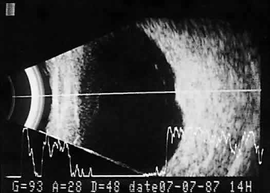
Fig. 12. Contact B-scan and simultaneous A-scan: choroidal hemangioma. Ultrasonically heterogeneous tissue shows strong reflectivity at all levels, appearing white in B-scan gray scale.

Calcification in any type of tumor tissue creates a strong acoustic interface, resulting in high-amplitude A-scan patterns as well as white echoes in B-scan imaging. Behind the area of calcification, there is usually partial or complete shadowing of the sclera and orbital fat. Bony tumors of the choroid, some retinoblastomas, and drusen of the optic 
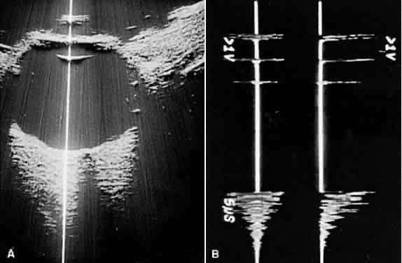
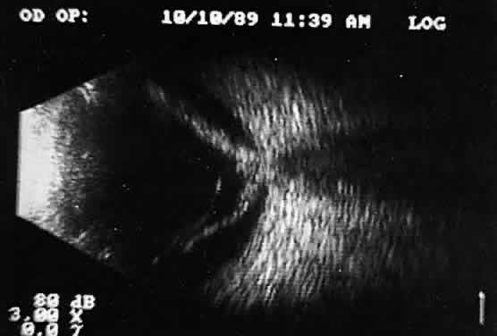
nerve head are typical examples where calcification may be found (Fig. 13).

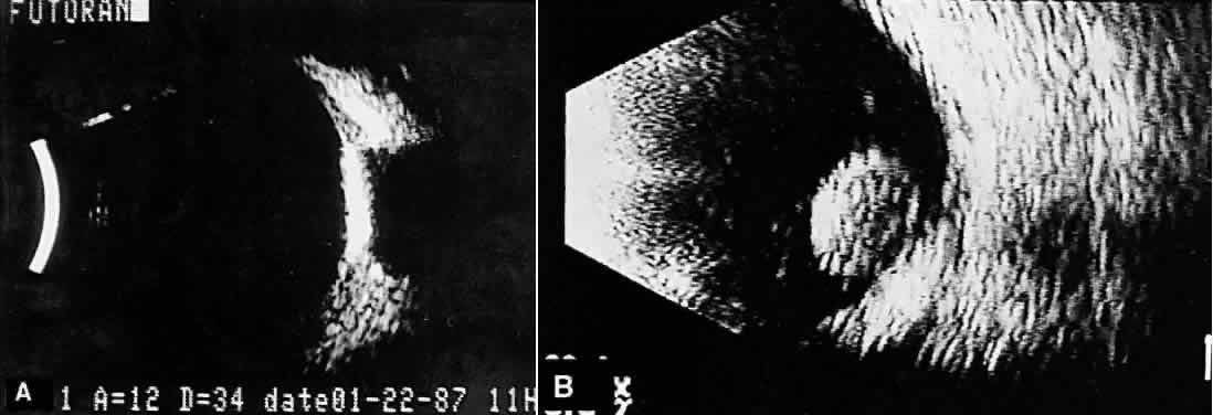
Fig. 13. Contact B-scans. A. Choroidal osteoma, demonstrating orbital tissue shadowing. B. Dislocated lens. Note shadowing of orbital tissues directly behind the highly reflective lens.

Unfortunately, there are far more tumor types than there are different ultrasound patterns, and many mass lesions, both benign and malignant, have similar ultrasound appearances. Further, the echo patterns change from one area to another within the same mass lesion. Although much rhetoric swirls in the ophthalmic literature concerning the quality of a variety of instruments, the techniques used, and the expertise of the examiner, the ultrasonic patterns of many tumors simply do not demonstrate differentiating features. In such situations, the ultrasound examiner must hedge the diagnosis, compiling a list of possibilities rather than one. On occasion, interpretation is simply not possible with any degree of reliability.

Some ultrasonographers prefer to use A-scan alone without simultaneous B-scan imaging for their tissue pattern interpretation.11 Separate A-scan units, some of which are packaged as an additional module housed in a simultaneous B-scan and A-scan instrument, are available. The separate units use modified amplifiers and are standardized against special test phantoms to permit comparison of results from one device to another.12,13

TRAUMA AND FOREIGN BODY EVALUATIONS

Ultrasound examinations for ocular trauma and intraocular foreign bodies are among the most difficult, for a variety of reasons (Figs. 14 and 15). The examiner is often presented with recently injured, unstable, or open globes with multiple complex injuries. Extreme care is necessary to avoid undue pressure during ultrasound evaluation, and concerns for contamination are significant. Understandably, probe contact is often minimized, and unless additional sterile methylcellulose solution is used to improve signal transfer, less-than-optimal images result. These poor-quality images are difficult or impossible to interpret, especially in opaque media situations with multiple abnormalities. Further, patient noncompliance and the examiner's inexperience frequently lead to incomplete examination, limiting 3D analysis.

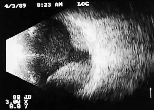
Fig. 14. Contact B-scan: choroidal hemorrhage/vitreous hemorrhage secondary to blunt trauma.

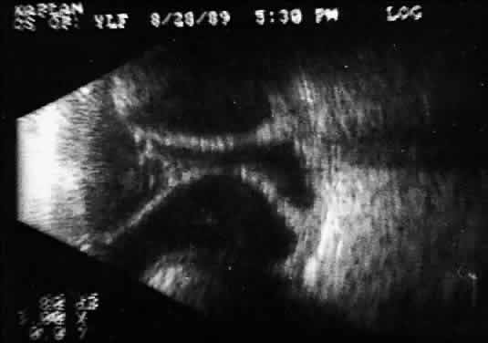
Fig. 15. Contact B-scan: large choroids (anteroposterior view) and portion of scleral implant (at bottom of display screen).

Despite the difficulties, there are several helpful concepts that aid in the examination of trauma cases:

  1. Always examine the globe visually (by slit-lamp technique preferably before ultrasonography) to determine if ocular integrity has been disrupted anteriorly. The possibility of a posterior nonvisible ocular wall rupture must also be considered.
  2. Clean the examining probe with soap, water, and alcohol, and use skin contact rather than scleral contact whenever possible.
  3. Ultrasonically examine the normal globe first to gain patient confidence.
  4. Use sterile methylcellulose solution to permit good signal transfer with less probe contact pressure.
  5. Take your time and be extremely gentle.
  6. Consider every trauma patient a potential foreign body patient.
  7. Radiography for foreign bodies should be part of every evaluation of ocular trauma resulting in opaque media and preferably should be done before ultrasonography.

Ocular and orbital foreign body patients require the most careful ultrasonic evaluation, as well as multiple ancillary tests, to provide sufficient diagnostic information. Like ocular trauma, these injuries usually occur unexpectedly and involve high-velocity projectiles. Patient histories are understandably poor or intentionally misleading. Because most foreign bodies are metallic and visible radiographically, appropriate head position for anteroposterior and lateral x-rays of the involved eye and orbit is critical. Routine radiographic imaging quickly supplies information concerning the number, size, and shape of metallic foreign bodies, as well as the presence of any intraocular air. Small bubbles that enter the globe at the time of injury and remain within the vitreous can be confused ultrasonically with small metallic foreign bodies. The large acoustic impedance mismatch between vitreous and air is similar to that between vitreous and metal.

Computed tomography scans are extremely helpful in foreign body localization, although it is often difficult to pinpoint the exact intraocular or extraocular position of metallic foreign bodies close to the ocular wall. Metal detection devices add information about the magnetic or nonmagnetic properties of intraocular metallic foreign bodies. Until the magnetic qualities of any potential intraocular foreign bodies are determined, magnetic resonance imaging should not be performed.

Ultrasound evaluation in patients with intraocular foreign bodies provides extremely useful additional information concerning associated ocular injuries and another method for localization, especially with nonmetallic intraocular foreign bodies not visible using x-ray techniques. Ultrasonically, foreign bodies have great reflectivity once the examining beam is placed perpendicular to a reflective surface of the foreign body. These abnormalities remain visible even with extreme attenuation of the examining signal (Fig. 16). Many metallic foreign bodies, especially those that are round or spherical, demonstrate “ringing,” a string of reflections that extend posterior to the foreign body in the form of a cometlike tail. Ringing is an ultrasound artifact produced by multiple “ping-pong” reflections of sound pulses within the foreign body before they return to the examining probe. The string of returning echoes produces an unusual display image.

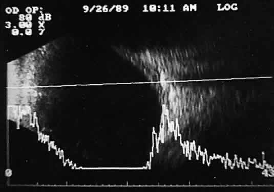
Fig. 16. Contact B-scan and simultaneous A-scan: “buried” choroidal metallic foreign body. Note strong B-scan gray-scale image and high A-scan echo amplitude.

When combined with radiographic information and metal localization technique, ultrasonically derived information aids enormously in the clinical evaluation of the patient with an intraocular foreign object. However, ultrasound alone is not sufficient to rule out a foreign object.

PHTHISIS

Once the globe has become small and shrunken, ultrasound evaluation becomes nearly impossible. Often, calcifications of a variety of ocular tissues make signal transfer difficult. General landmarks become obscure, and interpretation is unreliable. Small tumor identification in such situations is usually beyond the scope of reason.

ORBITAL ULTRASONOGRAPHY

Orbital ultrasonography is far more complex than ocular evaluation for a number of reasons. The shape and depth of the orbit make access for diagnostic ultrasound techniques more difficult. Ocular examinations are usually performed with 10-megacycle probes or higher frequencies. Lower ultrasound frequencies (5 to 8 megacycles) are often used to penetrate to orbital tissue depths. Lower-frequency probes have less resolution capability. Further, recognition of abnormalities within orbital tissues is more difficult because orbital tissues are highly reflective, making the appearance of subtle gray-scale changes in B-scan or amplitude changes in A-scan more difficult to appreciate against highly reflective tissues. Nevertheless, a vast quantity of literature is available concerning orbital technique and tissue characterization.8,9,14,15

In general, orbital ultrasonography is most useful in the evaluation of patients with exophthalmos related to a number of diseases, including primary and secondary tumors of the orbit, inflammatory diseases, and changes secondary to thyroid disease.

The displacement of orbital fat by more homogeneous tumor tissue is appreciated more readily in B-scan imaging. Tissue differentiation is better appreciated with simultaneous A-scan or standardized A-scan techniques. Two caveats are important: orbital interpretation is not for the novice, and examination of the deeper portions of the orbit, including the orbital apex, is usually best performed by other techniques, such as computed tomography or magnetic resonance imaging. Inflammatory conditions such as pseudotumor can involve a variety of orbital tissues, causing infiltration and thickening of the extraocular muscles, as well as space-occupying lesions within the orbital fat. Frequently, inflammatory exudate accumulates in the potential space between Tenon's capsule and the sclera. Such accumulations are easily detected during ultrasonography as dark, relatively echo-free spaces just outside the strong scleral echo.

Thyroid orbitopathy and exophthalmos are also frequently associated with thickening of the extraocular muscles, as well as other changes of the orbital contents.

POSTERIOR VITREORETINAL INTERFACE EVALUATION

Recent improvements in image quality and fused, real-time display have made ultrasound image interpretation easier for every ultrasonographer. Visualization of subtle changes such as movement and recognition of the posterior formed vitreous hyaloid are now possible, even in clear media situations. These clear vitreous structures, which are often exceedingly difficult to appreciate optically, can be recognized ultrasonically after a relatively short period of training (Fig. 17). Clinically, establishing the position of the posterior hyaloid is important in evaluating a variety of vitreous retinal disorders, such as macular holes, tractional detachments, and partial or complete vitreous separations.16,17

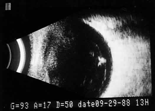
Fig. 17. Contact B-scan: posterior formed vitreous face separation, with prominent Weiss ring evident.

Back to Top
3D TOMOGRAPHIC ULTRASONOGRAPHY
Recent improvements in computer technology and digital B-scan devices have permitted the development of tomographic (3D) static displays. The new devices, often called 3D ultrasound instruments, increase understanding of complex topographic information (Fig. 18). Sophisticated software permits measurements of captured images (linear, area, and volume) as well as surface renderings18,19 (Figs. 19 and 20). Kinetic (real-time) information is not yet available in 3D and continues to be obtained during kinetic B-scan examinations performed before 3D image capture.

Fig. 18. 3D tomographic ultrasonogram software permits a combined tomographic 3D coronal/sagittal view of extensive choroidal detachment involving the anterior and postequatorial regions of the eye.

Fig. 19. 3D tomographic ultrasonogram. Area and volume measurement tracings are possible using software, as seen in this outlined melanoma.

Fig. 20. 3D tomographic ultrasonogram: linear measurement of a melanoma height derived from tomographic B-scan.

Back to Top
PRESERVATION AND DOCUMENTATION
Contact ultrasound information is best preserved on videotape, using an oral voice-over description to identify probe positions. Occasionally, more sophisticated split-screen special effects generators can be used, permitting simultaneous views of the ultrasound examination with an image of the probe position. The most common preservation methods involve Polaroid photography of specific frozen images chosen during contact examination. Unfortunately, these photographs document only the still images and are not of great value for future reference or independent analysis. Polaroid film lacks good gray scale, so subtle B-scan information is lost. Further, contact real-time kinetic ultrasonography is a dynamic examination that cannot be appreciated or preserved by still photography.

For immersion scanning (waterbath technique), photographs can be used to preserve information; with 35-mm gray scale, review is possible. Immersion scanning, unlike contact scanning, provides images that are derived from an anteroposterior waterbath position. A micrometer device on the examining probe permits sequential still photographic documentation. Dynamic real-time scanning is more difficult with the immersion technique, which relies on rapid multiple manual sweeps of the hand-controlled probe to provide real-time imaging. Real-time changes are best appreciated with motor-driven probes and preserved for future reference on videotape.

Back to Top
REFERENCES

1. Mundt GH, Hughes WF: Ultrasonics in ocular diagnosis. Am J Ophthalmol 41:488, 1956

2. Okasala A, Lehtilen A: Diagnostic value of ultrasonics in Ophthalmology. Ophthalmologica 134:387, 1957

3. Baum G, Greenwood I: The applications of the ultrasonic locating techniques to ophthalmology: I. Reflective properties. Am J Ophthalmol 46:319, 1958

4. Baum G, Greewood I: The applications of ultrasonic locating techniques in ophthalmology: II. Ultrasonic slit-lamp in the ultrasonic visualization of soft tissues.Arch Ophthalmol 60:263, 1958

5. Purnell EW: Intensity modulated (B-scan) ultrasonography. In Goldberg RE, Sarin LK (eds): Ultrasonics in Ophthalmology: Diagnostic and Therapeutic Applications, p 102. Philadelphia, WB Saunders, 1967

6. Bronson N: Development of a simple B-scan ultrasonoscope. Trans Am Ophthalmol Soc 70:365, 1962

7. Coleman DJ, Konig WK, Katz L: A hand-operated ultrasound scan system for ophthalmic evaluation. Am J Ophthalmol 68:256, 1969

8. Coleman DJ, Lizzi FL, Jack R: Ultrasonography of the Eye and Orbit. Philadelphia, Lea & Febiger, 1977

9. Dallow RL (ed): Ophthalmic ultrasonography: Comparative techniques. Int Ophthalmol Clin 19:4, 1979

10. Byrne SF, Green RL: Examination techniques for the orbit: Kinetic echography, p 276. In Ultrasound of the Eye and Orbit. St. Louis, Mosby-Year Book, 1992

11. Ossoinig KC: Quantitative echography: The basis of tissue differentiation. J Clin Ultrasound 2:33, 1974

12. Ossoinig KC: The first standardized system for echo-ophthalmology [German]. In Massin M, Roujol J (eds): Diagnostica Ultrasonica Ophthalmologia (Proceedings of SIDUO IV, Paris, 1971), p 131. Paris, Centre National d'Ophthalmologique des Quinze-Vingts, 1973

13. Ossoinig KC, Steiner H: Standardization in echography of the eye [German]. Graefes Arch Klin Ophthalmol 169: 2451, 1966

14. Coleman DJ: Reliability of ocular and orbital diagnosis with B-scan ultrasound. II. Orbital diagnosis. Am J Ophthalmol 74:708, 1972

15. Dallow Rl, Coleman DJ: Ultrasonic evaluation of orbital disorders. In Jakobiec FA (ed): Ocular and Adnexal Tumors. Birmingham, AL, Aesculapius, 1978

16. Fisher YL, Slakter JS, Friedman RA, Yannuzzi LA: Kinetic ultrasound evaluation of the posterior vitreoretinal interface. Ophthalmology 98:1135, 1991

17. Fisher YL, Slakter JS, Yannuzzi LA, Guyer DR: A prospective natural history study and kinetic ultrasound evaluation of idiopathic macular holes. Ophthalmology 101:5, 1994

18. Downey DB, Nicolle DA, Levin MF, Fenster A: Three-dimensional ultrasound imaging. Eye 10:75, 1996

19. Jensen PK: Ultrasonographic three-dimensional scanning for determination of intraocular tumor. Acta Ophthalmol Supplement 204:23, 1992

Back to Top