Chapter 3
Principles and Basic Techniques for Ocular Microsurgery
MARIAN S. MACSAI, ALLISON A. JENSEN and JOHN W. YANG
Main Menu   Table Of Contents

Search

SURGICAL SETUP
PREPARING THE EYE FOR OCULAR MICROSURGERY
MICROSURGICAL INSTRUMENT TECHNIQUE
VISCOELASTIC MATERIALS
SUTURES: WOUND CLOSURE
CLINICAL EXAMPLES
REFERENCES

As is true with any surgical procedure, the outcome of ocular microsurgery depends on various factors,which include the surgeon's technical skill, experience, knowledge of the basic techniques, and surgical judgment, as well as appropriate anesthesia, equipment, and instrumentation. This chapter introduces the beginning surgeon to the principles and basic techniques that are necessary to perform ocular microsurgery.

Microsurgery is distinctly different from general surgery.1 The operating microscope forces the surgeon to assume a particular posture that often must be maintained for several hours; this immobility sometimes hinders certain manipulations. The surgeon must understand this immobility and learn to work around it. The visual field is restricted, as is the space available for manipulation between the microscope and the operative field. The surgeon must become familiar with this spatial limitation and learn to manipulate instruments while visualizing them only through the operating microscope's objectives. Mastering the principles and basic techniques of ocular microsurgery is gratifying. The resulting surgical precision is elegant in both its technical and visual components.

Back to Top
SURGICAL SETUP

MICROSCOPE POSITIONING

The operating microscope consists of the following elements: oculars, beam splitter, magnification system, and objective (Fig. 1). The microscope may be mounted on the ceiling or on a mobile floor stand. Familiarity with the microscope is essential. To thoroughly understand the alignment of the movable parts of the microscope, the surgeon must take the time to disassemble and reassemble the apparatus. In addition, the beginning surgeon must become familiar with every rheostat and bulb on the operating microscope to compensate if an unexplained change in the illumination occurs during the surgical procedure. Both focus and magnification should be adjustable with a remote foot control (Fig. 2). The optical axis of the microscope on the operating field also may be adjusted with a foot pedal. The surgeon must ensure that the X-Y-Z centering buttons on the microscope have been reset before the start of any case. When the same operating theater is used repeatedly, a ceiling-mounted microscope requires little preparation on the part of the operator and permits rapid change of patients between operations under antiseptic conditions. It is beyond the scope of this chapter to describe the various types of microscopes available; however, surgeons selecting an operating microscope should be familiar with at least the major principles of function.

Fig. 1. The operating microscope has four essential elements: the oculars (A), the beam splitter (B), the magnification system (C), and the objective (D).

Fig. 2. View of the remote foot control. The focus (A), magnification (B), and optic axis of the microscope (C) may be adjusted. The joy stick is used to adjust the optic axis of the microscope. The operating microscope lights and room lights also may be adjusted by use of the foot pedal (D).

SURGEON'S POSITIONING AND POSTURE

During an operation, the surgeon should sit in a natural position, leaning slightly forward, with a straight back and relaxed shoulders. Both feet should be flat on the floor (Fig. 3). This posture and the surgeon's physique determine the optimal viewing direction in which the eyepieces should be inclined. Swivel-mounted oculars permit appropriate adjustments. In principle, it is possible to align the microscope obliquely on the operating field. This positioning may be required in special situations; in practice, a vertical alignment is customary. However, the oculars may be set at an oblique position to increase the surgeon's comfort. The inclinable binocular tube can be adjusted for the most comfortable direction of gaze (Fig. 4). The entire surgical field can be surveyed simply by dropping one's gaze to the operative field.

Fig. 3. Ideally, during ocular microsurgery, the surgeon should sit in a natural position with a straight back, leaning slightly forward. The shoulders should be relaxed. The oculars are set in an oblique position such that the angle of inclination provides comfortable alignment for the surgeon.

Fig. 4. The adjustable inclinable binocular tube (oculars) may be adjusted (arrow) for the most comfortable direction of gaze for the surgeon. In this manner, the entire surgical field is not in line with the surgeon's gaze.

The working distance, which is the distance from the oculars to the operating field, should lie within the reasonably comfortable range of 350 to 400 mm. This optimal distance may be exceeded with some types of microscopes if the beam splitter is interposed between the oculars and the body of the microscope. The actual space available for manipulation is determined by the distance between the objective lens and the operative field and should not be less than 150 mm.2

The operative field is rarely aligned with the direction of the surgeon's gaze as he or she viewsthrough the eyepieces (Fig. 5). This positioning should not impair eye-hand coordination. Movements of the surgeon's instruments are precisely controlled optically from the moment they appear within view under the microscope. In fact, within the modest range of magnification used in ophthalmic surgery, the surgeon's control and manipulation are enhanced in direct proportion to the magnifying power selected.

Fig. 5. The surgeon may view the entire operative field only by gazing down or looking around the microscope. As a result, the surgeon must develop eye-hand coordination to move the instruments within the surgical field viewed through the microscope. After the instruments have been visualized within the surgical field, they may be controlled precisely within the view under the microscope.

The surgeon must be able to survey the entire surgical field beyond the microscope by dropping his or her gaze without retreating appreciably from the oculars. Inclinable ocular tubes are useful in this respect. The surgeon may elect to wear a spectacle correction to compensate for any refractive error or presbyopia. Surgeons who have a spherical refractive error may be more comfortable having their oculars adjusted to allow for their spectacle correction. The primary ophthalmic surgeon may be seated at the head of the operating table, and the assistant ophthalmic surgeon seated to the side of the operating table (Fig. 6). The assistant should always be seated at a right angle to the surgeon on the same side as the operated eye. For example, when operating on the right eye from the superior position, the assistant sits to the surgeon's right. However, if the primary surgeon is taking a tempo-ral approach to the right eye, the assistant sits to the surgeon's left, at the head of the table. With this positioning, instrument passing between the surgeon, the assistant, and the scrub nurse can be done with the greatest ease. However, instruments frequently need to cross the surgical field, and the assistant may need to make some adjustments to avoid interrupting the passing of instruments from the surgical field.

Fig. 6. The assistant should be seated at a right angle to the surgeon on the same side as the affected eye. For example, when operating on the left eye, the assistant sits to the surgeon's left. The surgical scrub technician is positioned over the patient's abdomen. Instruments frequently are passed across the surgical field to the operating surgeon. The assistant must make adjustments to avoid interrupting the passing of instruments from the surgeon to the scrub technician and possible resultant needle sticks.

Before the surgical procedure may begin, the microscope must be focused precisely. There is a tendency to focus down during intraocular procedures as the patient's head settles in the headrest and as the eye softens. Therefore, the microscope should not be set in the middle of the range of focus; rather, it should be set two thirds of the way toward the top of the range of focus to allow for a greater range of downward focus during the procedure. The microscope should be adjusted with a high power of magnification, taking advantage of the correspondingly narrowed depth of field to permit a more accurate focus. The magnification is subsequently reduced to a power appropriate to the procedure. This simple maneuver ensures a good depth of focus at normal working magnification, allowing for visualization of both the tips of the instruments and the suture or tissue. The microscope should be raised until the field is out of focus and then lowered to the point at which the surgical plane is in focus. At this point, the assistant should adjust the oculars to focus on the same surgical plane. This maneuver prevents unnecessary accommodation during the surgical procedure. If the surgeon is considerably younger than the assistant, limiting accommodation is particularly important.

FOOT PEDAL POSITIONING

As though playing an organ, a surgeon frequently must operate a number of foot pedals when performing microsurgery. In addition to the foot pedal for the operating microscope, other foot pedals may be available for cautery, irrigation-aspiration, phacoemulsification, mechanical vitrectomy, and lasers (Fig. 7). The surgeon must be comfortable and stable on the operative stool so that both feet may be used to manipulate these pedals. For the shorter surgeon, it may be necessary to place the foot pedals on a platform. The surgeon should become familiar with using the pedal for the operating microscope on the same side for all procedures. Most surgeons prefer to control the microscope with their left foot and thus leave their right foot free to operate any ancillary pedals needed for cautery, irrigation-aspiration, or phacoemulsification. When using linear aspiration or phacoemulsification, precise control of the foot pedal is essential. Because many surgeons use their right foot to drive a car, they use the same right foot to operate these pedals. However, each surgeon will have an individual preference.

Fig. 7. Numerous foot pedals must be set up under the operating table. The surgeon must be able to operate these pedals without seeing them. The operating microscope remote control foot pedal is shown on the left, with an irrigation/aspiration, vitrectomy, and phacoemulsification control on the right. The small black pedal in the middle is used for cautery.

HAND POSITIONING AND SUPPORT

For microsurgical manipulation, maximum precision is required. To achieve this precision and a steady hand, the surgeon's hand should be supported. Support can be provided in the middle of the forearm with an armrest that is attached to the operating stool, or it can be provided directly behind the wrists with the use of a wrist rest that attaches to the operating table (Fig. 8). The wrist rest should be set to the height of the patient's lateral canthus. Alternatively, the surgeon may rest their hands on the brow and cheek of the patient during the surgical procedure. Whatever the form of support, it should be used to support the hand and not to stabilize the surgeon while leaning forward. The surgeon should be well centered on the stool with their shoulders relaxed such that their arms rest gently on the support. When operating, the surgeon must achieve a light touch so that their hands are “floating,” not leaning on the field.

Fig. 8. A. A wrist rest can be set up to stabilize the surgeon's hands. During the procedure, the height of the wrist rest should be set to the level of the patient's lateral canthus. B. Depending on the size of the surgeon's hand, a wrist rest may provide support for the wrist or the hand.

Back to Top
PREPARING THE EYE FOR OCULAR MICROSURGERY
The first step in ocular microsurgery is maintaining separation of the eyelids. This separation involves not only opening the lids beyond their natural opening but also retracting the lids from the globe to relieve the natural deformation of the globe, which may be caused by the eyelids. In addition, should the patient inadvertently attempt to blink during surgery, this action will not result in increased intraocular pressure (IOP). Lid separation may be maintained by traction sutures or lid specula. Traction sutures are effective in obtaining lid separation and retraction (Fig. 9). Traction sutures are most effective when passed through the tarsus; however, there is a tendency for the lids to evert. The tarsus lid speculum may be either self-retaining or of the spring-tension type (Fig. 10). In addition, individual lid hooks or retractors that are maintained by clamping to the head drape may be used. Each speculum offers certain advantages. Some specula, which offer the additional option of aspiration, may be attached to suction devices to keep the fornices dry during the procedure. The spring-tension wire or solid-blade speculum opens the lids to the extent of the spring tension. However, spring tension is not adjustable, and the speculum may rotate intraoperatively. Many lid speculum designs are available with a screw clamp design. A lid speculum with a screw clamp device, such as the Schott lid speculum, allows the lids to be separated and retracted off the globe when the lid hooks are everted individually.5 This lid speculum provides an excellent surgical field without resulting in increased IOP. This feature is especially important if the assistant inadvertently leans on the lid speculum during the operation. In another type, the Jaffe lid speculum, the upper and lower lid hooks are individually secured to the head drape. This type of speculum offers some advantage when operating on patients with a prominent brow or deep-set orbits. The wire speculum may be formed to the patient's brow to allow for better retraction of the upper lid. With any of these methods, it is theoretically possible to disinsert the levator muscle from the superior aspect of the tarsus, resulting in postoperative ptosis. Therefore, overretraction of the lids must be avoided.

Fig. 9. A traction suture is placed through the skin and tarsus to provide traction on the lid. However, there is a tendency for the lids to evert during the procedure.

Fig. 10. Various types of lid specula are available. One is the Schott lid speculum (A). An alternative is a screw-clamp speculum (B). A spring-tension wire speculum (C) or a solid blade speculum (D) opens the lids to the extent of the spring tension.

Back to Top
MICROSURGICAL INSTRUMENT TECHNIQUE

HOLDING INSTRUMENTS

Microsurgery requires fine control of instruments. To achieve this control, the surgeon must be familiar with the advantages of different instrument designs. Some surgical instruments have a serrated flat handle, others have a rounded knurled handle, and still others have a round serrated handle (Fig. 11). The serrated or knurled areas allow the surgeon a firmer grasp and tighter control of the surgical instrument. An instrument with a round, knurled handle may be rotated in the fingertips, allowing for greater flexibility during some procedures. For example, some types of tying forceps are designed with this option. In contrast, most ocular scissors have a flat serrated handle.

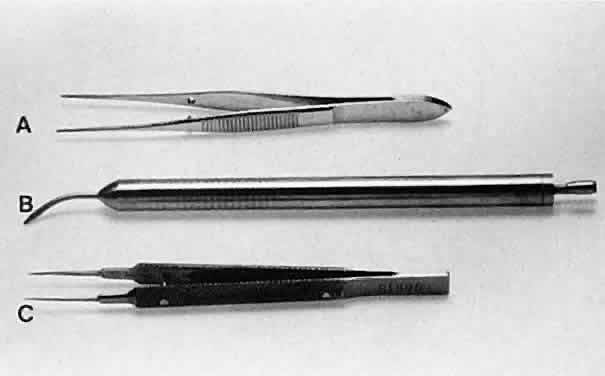
Fig. 11. Three surgical instruments with three handle styles. A. A flat serrated handle. B. A round serrated handle. C. A round knurled handle.

No surgical instruments are intended to be held like a pencil, resting in the crotch between the thumb and forefinger (Fig. 12).3 In conventional eye surgery, longer instruments usually are rested against the first metacarpophalangeal joint, with the thumb and first two fingers encircling the handle. Stability is achieved by resting the side of the fifth finger on the periorbital facial structures. This method of holding surgical instruments allows for rotation of the instrument between the fingertips, by flexing the fingers, or by rotating the wrist. Great mobility is necessary when using a needle holder (needle driver) to pass a needle through tissue. When the surgeon encounters resistance from the tissue, it is usually necessary for the surgeon to twist the wrist or apply counter pressure on the tissue at the exit site of the needle. Holding surgical instruments correctly provides the surgeon with increased flexibility and mobility. The serrations on the handle, regardless of style, allow the surgeon to hold the instrument lightly, but firmly. With the level of precision of currently available instruments, it is never necessary to grasp an instrument tightly. The tendency to grasp instruments tightly must be avoided because it decreases flexibility and increases fatigue of the hand and forearm muscles. Any resistance encountered when placing an instrument into or out of the eye is secondary to positioning of the instrument. Adjusting the angle of the instrument or your hands should allow easier placement of the instrument.

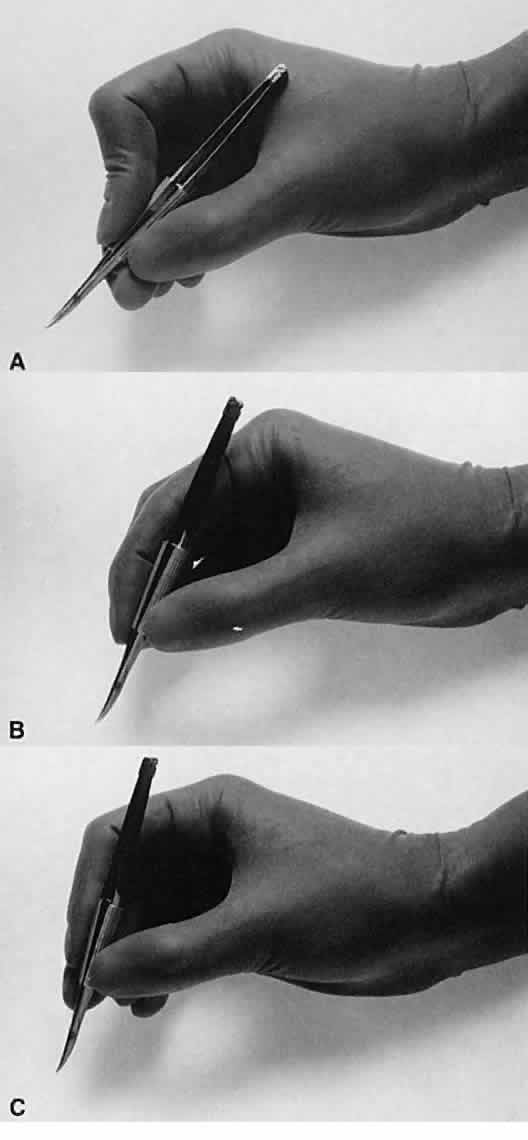
Fig. 12. A. A surgical instrument held like a pencil, resting in the crotch between the thumb and the forefinger. No surgical instruments are intended to be held in this manner. B. A longer surgical instrument held resting against the first metacarpophalangeal joint of the first finger, with the thumb and the first finger encircling the handle. This position allows for rotation of the instrument between the fingertips or by flexing the fingers or wrist. C. The surgical instrument is held between the thumb and fingertips of the second and third digits. This position allows for a more perpendicular positioning of the instrument on the eye.

Frequently, the beginning surgeon complains that an instrument does not hold a fine suture, such as 10-0 nylon. Often, this problem results from improper handling of the instrument. For example, the design of a surgical tie calls for the surgeon to apply pressure at the flat serrated handle to ensure that the tying platforms meet properly. If a torque or oblique force is applied to the tying forceps, the 10-0 nylon may be inadvertently sheared or may not be grasped tightly. To avoid this problem, various instruments have a guide incorporated into the handle. The guide requires proper alignment for the instrument to close (Fig. 13). The same difficulty may be encountered when using a locking needle holder. The lock will hold only if the needle holder is positioned properly within the surgeon's fingertips and the force applied is not oblique to the handle. If the forces applied to the instruments exceed those provided for in its construction, the components of the instrument will bend and the jaws will not appose correctly (Fig. 14).4 Instruments have been designed to be held at the serrated portion of the handle. Holding them more anteriorly or posteriorly alters the force applied and may result in malfunctioning of the instrument.

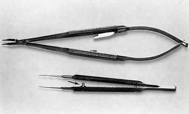
Fig. 13. A surgical tie is shown on the bottom. A guide is incorporated into the handle (arrow). The guide ensures proper alignment for the instrument to close. On the top, a locking needle holder is shown. The lock will hold only if the needle holder is positioned properly in the surgeon's fingertips and the force applied is not oblique to the handle.

Fig. 14. When a proper degree of force is applied to the instrument, the tips will align properly. However, if greater forces are applied, the instrument bends and the jaws do not appose correctly.

GRASPING TISSUE

Before using a forceps to grasp tissue, the surgeon must have a clear understanding of the mechanism by which the instrument holds tissue and the extent of damage caused by the instrument. In ophthalmology, three instruments are used to grasp tissue: the smooth forceps, the toothed forceps, and the spatula (the hook).

Smooth forceps (i.e., forceps without teeth) must be used when handling delicate tissues (Fig. 15). For example, smooth forceps are necessary when working with tissue that must not be punctured or damaged, such as the conjunctiva during a trabeculectomy. An absolutely smooth forceps with no defined grasping surface usually is ineffective when handling the conjunctiva. Such a forceps (also called a tying forceps)—is—used to hold fine suture. Instead, serration of the grasping surface provides increased friction without damaging the tissue. It is effective in handling the conjunctiva because the conjunctival surface can conform to the ridges of the serration. Criss-cross serrations permit traction in all directions. If one attempts to use a serrated forceps on rigid material, such as the sclera, only the tips of the serration will hold the tissue, reducing the contact area and the effectiveness of the forceps (Fig. 16). Therefore, toothed forceps must be used to grasp the sclera effectively.

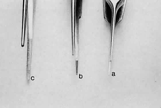
Fig. 15. Three different smooth forceps. On the right is an absolutely smooth forceps (A). In the middle is a grooved forceps (B). On the left is an instrument with a serrated platform (C). The instrument on the right is used to grasp fine suture, whereas the instrument on the left is more commonly used to handle conjunctiva or thin tissue that can conform to the ridges of the serration.

Fig. 16. When a smooth forceps is used to grasp rigid material, only the tips of the instrument hold the tissue, thus reducing the contact area and effectiveness of the forceps. A. When a smooth forceps is used to grasp rigid sclera, the forceps slips. B. Toothed forceps may be used more effectively to grasp rigid tissue such as the sclera or cornea.

Toothed forceps can have teeth at a 90-degree angle (surgical forceps) or angled teeth (mouse-tooth forceps; Fig. 17). An example of a surgical toothed forceps is a 0.12-mm forceps; an example of a forceps with angled teeth is the O'Brien forceps. Microscopic examination of the instrument from the side determines tooth design. A toothed forceps is needed for tough tissue, such as the cornea or sclera, whereas soft tissues, such as the iris or conjunctiva, are better handled with a smooth forceps (see Fig. 16). Surgical toothed forceps may damage delicate tissue; however, these forceps exert a high degree of resistance, which is necessary for manipulating tougher tissues. Forceps with angled teeth can seize tissue lying in front of the end of the blades. For example, these forceps can be used to grasp the muscle insertion through the conjunctiva (Fig. 18). The forceps can grasp a minimal amount of tissue and produce minimal surface deformation, frequently without penetrating the tissue. The angle-tooth forceps can be useful for grasping the cornea during corneal transplant surgery or repair of corneal lacerations. If the teeth are dull or bent, the forceps become ineffective. The number and orientation of the teeth on a forceps affect the stability of fixation and tissue damage. Teeth angled at 90 degrees provide good fixation, but greater tissue damage than teeth angled at 45 degrees (mouse-tooth forceps). Increasing the number of teeth also increases the degree of tissue fixation. One example is the Thorpe corneal fixation forceps, in which the 90-degree teeth are in a 2 × 3 configuration. The Thorpe corneal fixation forceps has been modified with 45-degree angled 0.12-mm teeth in a 2 × 3 configuration, thus allowing for increased stability of tissue fixation, with limited tissue damage. When driving or passing a needle through tissue that is fixed with a toothed forceps, the forceps should be held such that the needle enters the tissue on the side of the forceps with the greatest number of teeth. In other words, when a Thorpe corneal fixation forceps is used, the needle should pass through the tissue on the edge that is secured by three teeth. This maneuver limits the twisting of the tissue as the needle is advanced through the tissue. Finally, an alternative is the Pierse-type forceps, which has no teeth but has a small hollow area immediately posterior to the tip. This hollow area allows for tissue displacement instead 
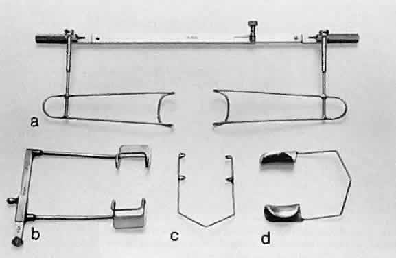
of the tearing of tissue that occurs with sharp-toothed forceps.

Fig. 17. Tooth forceps may be separated by the angle of insertion of the teeth. A. Forceps with teeth at a 90-degree angle. B. A mouse-tooth forceps with angled teeth. C. A Thorpe corneal fixation forceps with 45-degree angled 0.12-mm teeth in a 2 × 3 configuration. D. A Pierse-type forceps with no teeth but with a small hollow area immediately posterior to the tip.

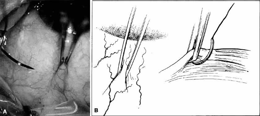
Fig. 18. A. Forceps with angled teeth can grasp tissue lying in front of the end of the teeth. A forceps with angled teeth is seen grasping the superior rectus muscle insertion through the conjunctiva before placement of a bridal suture. B. The muscle is pulled off the globe by the forceps, and the suture is allowed to pass beneath the body of the muscle.

A spatula has a uniform cross section throughout its length, which allows the instrument to be inserted through a small incision. Manipulation with the spatula may be performed at a site distant to the insertion site or place of incision. With the use of the incision as a pivot, the 
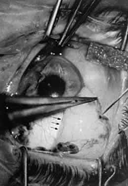
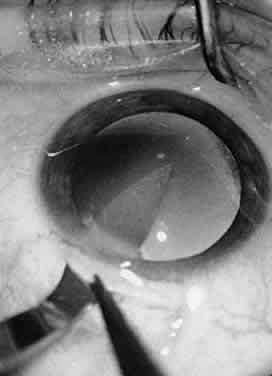
spatula may be used to separate tissues, such as iris adhesions (Fig. 19). Hooks are used to move tissue with a pulling or pushing motion. Sharp hooks usually are avoided in microsurgery because they tend to traumatize surrounding tissues. A simple hook may be used to push the iris tissue out of the way or to engage an intraocular lens (IOL) and rotate it into position (Fig. 20). A collar buttonhook can push and pull in any direction, but it must be inserted sideways so that it will not be caught on the wound edge.

Fig. 19. A spatula is used at a site distant from its insertion. The spatula is inserted through a small incision at the limbus. The tip of the spatula is placed between the anterior lens capsule and the iris. The spatula is rotated to lyse adhesions (synechiae) between the iris and the anterior lens capsule.

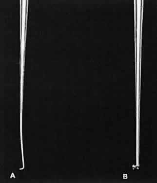
Fig. 20. Two hooks that may be used to move tissue with a pulling or pushing movement. A. A Sinsky hook. B. A Graether collar button. This hook can push and pull tissue in any direction, but it must be inserted sideways so that it will not catch on the wound edge.

INCISING TISSUE

Tissues are separated by one of two basic techniques: blunt dissection or sharp dissection. Tissue is cut with either a knife or a scissors. During microsurgery, it is essential for the surgeon to understand the concepts of the division of tissue and how this division is best accomplished with appropriate instrumentation.

Three major factors influence tissue dissection: the shape and sharpness of the instrument used, the properties of the tissue being cut, and the way in which the surgeon guides the instrument during the cutting process. The tissue itself has several properties, including thickness and sectility (the tendency of the fibers to be sectioned, rather than displaced, by a blade). Tension of the tissue also affects how easily the tissue can be cut. It is possible to vary the tissue tension by applying traction with a forceps. However, using a forceps may deform the tissue, making it necessary to alter movements of the blade to obtain the intended cut. The shape of the cut is determined by the path taken by the blade through the tissue. Unless otherwise directed, the blade will follow the path of least resistance when incising tissue. This path has been referred to as the preferential path. Deviations from the preferential path are made more easily by using only a small part of the blade to enter the tissue.4 When lamellar tissue (e.g., sclera, and especially cornea) is dissected, the resistance is lowest in the direction of the lamination, rather than at right angles to it.

Blunt dissection promotes use of lamellar tissue planes and is best chosen when tissue layers are being separated. In blunt dissection, tissue fibers are stretched and split to the point of separation. This technique is effective only when tissue planes exist. Therefore, blunt dissection must be performed in a potential tissue plane. The surgeon must be guided by the tissue planes and must not attempt to override or change them. Blunt dissection is achieved by advancing the scissors' tips and opening the scissors' blades, or by using a spatula.

Sharp dissection is needed to cut across the lamellae. It may be accomplished with either a single blade or a scissors. When using a blade, the surgeon must distinguish between cutting with the point of the blade or with the cutting edge of the blade (Fig. 21). The point of the blade is a versatile cutting instrument that can produce incisions of any shape. Because the blade point must be extremely sharp, blades are either disposable or constructed of highly resistant material (e.g., diamond). The surgeon can vary the amount of the cutting edge that penetrates the tissue to make a straight versus a curved incision (Fig. 22). For a straight incision, the blade should be held so that the maximum amount of the linear cutting edge comes between the edges of the incision. For a curved incision, a small amount of the blade surface should penetrate the tissue to allow for alterations in the direction of the incision.

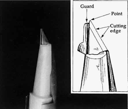
Fig. 21. A guarded blade. The cutting edge is distinguished from the point of the blade. The point of the blade is more versatile than the cutting edge for producing incisions of various shapes.

Fig. 22. The amount of the cutting edge that penetrates the tissue changes the shape of the incision. A. When the cutting edge penetrates the tissue, it is difficult to curve, which results in a straight incision. B. When the point of the blade is used, a curved incision is more easily made.

Scissors can be used in three ways to cut tissue: closing the blades, opening the blades, and advancing the tips of the blades. Two basic types of scissors are used in ophthalmic surgery: scissors with ringed handles and a simple screw joint, and scissors with a spring handle (Fig. 23). The blades of the scissors may be straight or curved. The ability of scissors to cut depends a great deal on the thickness of the tissue. In principle, scissors crush tissues before separating or cutting them. In thick tissues, such as full-thickness cornea and sclera, the profile of a scissors' cutting tissue has an S-shape (Fig. 24). This shape is most exaggerated in tissue that is not very mobile, such as the cornea and sclera.

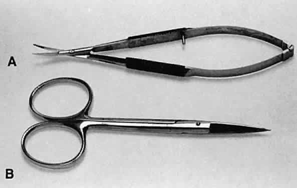
Fig. 23. Two types of scissors are used for most ophthalmic surgery. A. Spring-handle scissors. B. Ring-handle scissors with a simple screw joint. The blades may be straight or curved, and the scissors may be used for blunt or sharp dissection.

Fig. 24. When scissors are used to cut thick tissue, they crush the tissue before separating it. As the tissue is crushed, oblique forces are applied such that the incised tissue has an S shape when viewed in profile.

One potential problem with scissors is the tendency to produce a serrated edge. When the scissors are advanced and the direction of the cut is changed, or the tissue is compressed, a serrated edge results (Fig. 25). When the scissors' tips are closed completely, they penetrate completely into the tissue and produce a small lateral cut.4

Fig. 25. When scissors are used to cut tissue, it is important to avoid producing a serrated effect. A. Scissors are closed partially (arrows), reopened carefully, and advanced following the original direction of the cut. B. When the tips are closed completely, they will penetrate tissue and act as a cutting edge, producing a small lateral cut. This movement causes a serrated effect.

When using scissors to cut tissue, it is preferable to avoid producing a serrated edge. This may be avoided if scissors are closed partially, reopened, and carefully advanced in the original direction of the cut. Without removing the scissors from the wound, the blades are reapplied to the tissue and again opened and advanced in the original direction of the cut. This maneuver is important when making a large incision, such as in corneal transplantation or large incision cataract extraction. Therefore, when scissors are used to create a limbal wound, the inferior blade is inserted into the anterior chamber and the scissors are compressed partially, released, and advanced. Care must be taken to avoid changing the direction of the cut, closing the scissors completely, or removing the scissors from the wound before completion. Using this technique will avoid an irregular serrated incision.

All spring-handled scissors are designed such that applying pressure on the posterior handle of the scissors controls the upper blade of the scissors. The surgeon must understand this concept when incising tissue in situations in which the lower blade is inside the eye and the upper blade is outside the eye. Obviously, excessive movement of the lower blade that is inside the eye should be avoided to prevent damage to the intraocular structures. Troutman-Katzin and Moore-Troutman scissors are designed so that the lower blade remains immobile and only the upper blade may be compressed to incise tissue.

Scissors are a safe instrument to use because they divide only the tissue lying between the blades, avoiding inadvertent incisions. In addition, scissors are versatile. The disadvantage of scissors is that very thick tissue can be difficult to incise. Making a preliminary partial-thickness incision before the tissue is cut with the scissors can reduce 
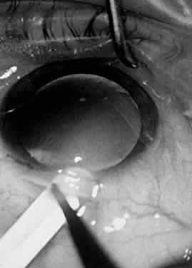
this problem.

Scissors also may be used surgically by opening the blades. This maneuver is employed primarily during blunt dissection (Fig. 26). In this procedure, the surgeon is cutting with the blade tips. Sharp points can force their way through tissue, whereas blunt tips act as a spatula and do not damage surrounding structures. When the surgeon dissects a conjunctival flap or into the sub-Tenon's space, blunt dissection is preferred. In addition, should the surgeon need to avoid disturbing the flaps (or a buttonhole), such as a conjunctival flap for a glaucoma procedure, the surgeon should not use scissors with sharp tips for blunt dissection. However, when the surgeon is working in an area that is scarred as a result of previous surgery, the use of sharp tips may be necessary.

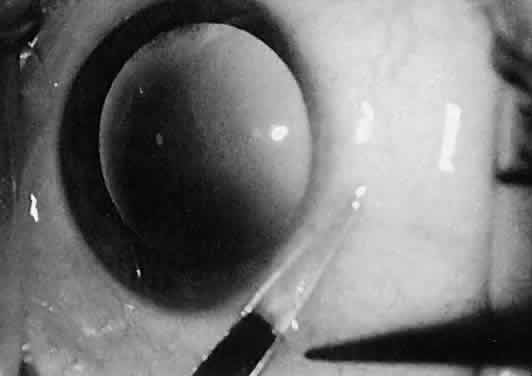
Fig. 26. The sharp points of scissors are forcing their way through the subconjunctival space. Opening the scissors will result in blunt dissection of the subconjunctival space.

SUTURING TISSUE

Three instruments are necessary to suture tissue properly. The first is the instrument to grasp the tissue, either a smooth or a toothed forceps. The second is the needle holder (needle driver). The third is the tying forceps. In some situations, toothed forceps can be combined with a tying platform to create multipurpose forceps (Fig. 27). It is a basic surgical principle that for any needle to pass through tissue, the resistance of the needle and the needle holder must exceed that of the tissue through which the needle is passing. In ocular microsurgery, tissue resistance is low, compared with that encountered in general surgery; however, if the needle holder is used improperly, the danger of needle deformation is great because ophthalmic needles in general are very delicate. Ideally, the cross-section of the needle holder should match the curvature of the needle, thus preventing needle deformation when the needle is driven through tissue. Therefore, large, locking needle holders may be used to grasp large needles, and fine needle holders should be used for ultrasharp needles. With very fine, flat jaws, there is little danger of needle damage when ultrasharp needles are passed through tissue with minimal resistance. Ideally, the needle holder should grasp the needle shaft one half to two thirds of the way from the needle tip (Fig. 28). The needle is likely to flip if it is not seated at a right angle to the needle holder. When the needle is properly seated in the needle holder, at a 90-degree angle, the surgeon must flex the wrist to increase mobility and pass radial sutures in all meridians. Simply dropping the shoulder of the arm that is holding the needle holder increases the surgeon's range of motion considerably. Lowering the magnification during suturing enlarges the field and thus allows better manipulation of the ties and ease of suturing.

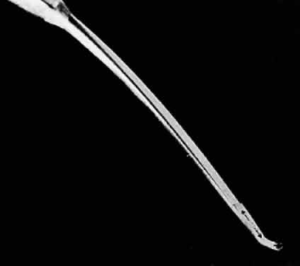
Fig. 27. A combination forceps in which a toothed forceps also has a tying platform (arrows) to create a multipurpose forceps.

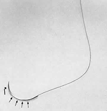
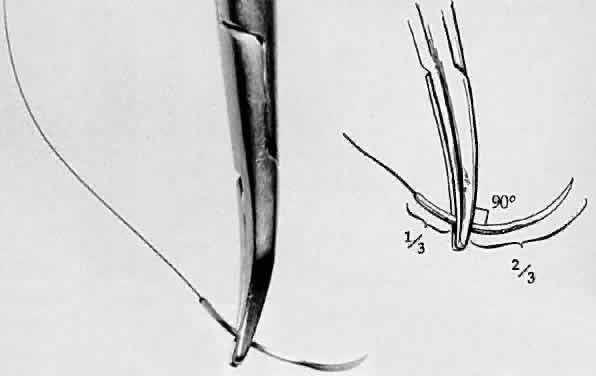
Fig. 28. A needle holder is shown grasping a surgical needle approximately two thirds of the way from the head of the needle to the suture. The needle is seated properly in the needle holder at a 90-degree angle.

Tying forceps must avoid damage to delicate suture materials yet grip the suture firmly. It is important for the surgeon to keep in mind that the suturing of tissue should not be done at the expense of overly stretching the tissue to be sutured. Instead, the goal of the surgeon should be to ensure that the tissue could be apposed without being stretched. Furthermore, tissue edges must be respected. Using rounded side edges will avoid damage to suture materials; however, proper handling of the forceps is key. The tip of the tying platform should be used to pick up the suture. If the suture material cannot be grasped, the tying platform should be inspected for incomplete closure due to damage of the platform or incarceration of foreign matter. However, overcompression of the handle may cause the tying platform to gape (see Fig. 14). If the suture is loaded into the tying forceps longitudinally so that the suture becomes simply an extension of the forceps, it is much easier to wrap the suture around another tying platform to secure the tissue (Fig. 29).

Fig. 29. A. Suture is loaded into tying forceps longitudinally on the top so that the suture becomes an extension of the forceps. This positioning increases the ease with which the surgeon wraps the suture around the tying platform. B. The suture is loaded obliquely in the tying platform. This placement frequently makes wrapping the suture around another tying forceps more difficult.

HEMOSTASIS

Hemostasis commonly is achieved by applying heat to tissue, which causes coagulation. Cauterization may range from interruption of blood flow of vessels to blanching of tissue, gross charring of tissue, and in extreme cases, tissue contraction (Fig. 30). The only way to monitor the application of heat is by anticipating the power needs and visualizing the results. Care in this area is key to controlling the delivery of heat to tissues. Excessive heat may cause tissue contraction and wound deformation. Heat is generated in tissues by monopolar or bipolar diathermy. Monopolar miniature diathermy probes are used for intraocular coagulation. Bipolar diathermy is used to generate heat in tissues either by grasping the tissue to be coagulated or by applying indirect bipolar diathermy through a liquid film. With either method of delivery, the bipolar diathermy unit requires that the tissue to be coagulated remain between the probes of the diathermy unit. Therefore, the forceps tips of the diathermy unit must be closely 
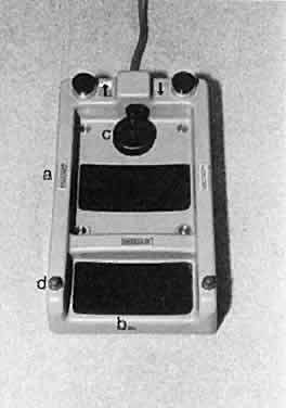
approximated but not touching. As soon as the bleeding vessel coagulates, the foot pedal should be released to limit tissue contraction. Changing the voltage while keeping the space between the diathermy probes constant controls the diathermy. In this way, increased voltage results in increased energy delivery; however, in effect, keeping the voltage constant and bringing the probes closer together increases the energy delivered to the tissue. Delivery of excessive heat or energy causes significant tissue shrinkage that may result in wound deformation.

Fig. 30. Hemostasis achieved through cauterization provides for interruption of blood flow in vessels. The application of heat is monitored through visualizing results. Excessive tissue shrinkage should be avoided. Coagulation is visualized by the interruption of blood flow through the vessel.

Back to Top
VISCOELASTIC MATERIALS
In ophthalmic surgery, viscoelastic materials may be used for many different purposes. Viscoelastic materials are used to protect tissues by providing a protective coating. For example, in the anterior chamber, viscoelastic materials may be used to protect the endothelium during phacoemulsification. Viscoelastic materials also may be used to stabilize a space within the eye or to occupy a virtual space within the eye. Viscoelastic materials may be used to reform the capsular bag after cataract extraction, aiding in the insertion of IOLs (Fig. 31). Additionally, these materials may be used to separate adherent tissue layers when they are introduced through a cannula to lyse synechiae. In some instances, the viscoelastic material may be used to reappose tissues, for example, to replace a detached Descemet's membrane. Finally, a viscoelastic material may be used to occlude or seal the anterior chamber. This technique can be useful during repair of corneal lacerations or when applying tissue adhesive for small corneal perforations.10

Fig. 31. A viscoelastic material may be used to reform the capsular bag after cataract extraction. The viscoelastic material is used to stabilize a space within the eye or to occupy a potential space.

Various viscoelastic materials are currently in use. Largely, the various types of viscoelastic materials differ from one another in their molecular weight. For example, Viscoat brand viscoelastic has a higher molecular weight and therefore might be used when the surgeon needs to stabilize a space within the eye or to occupy a potential space within the eye. The higher molecular weight of the material enables more effective filling of the space and better maintenance of that space. However, the higher molecular weight of the viscoelastic makes it more difficult for the surgeon to remove the material from within the eye. Retained viscoelastic material has long been known to cause decreased function of the trabecular meshwork with a resultant increase in IOP. In the end, the surgeon must weigh the benefits of a higher-molecular-weight viscoelastic against the possibility of hindered trabecular outflow.

Back to Top
SUTURES: WOUND CLOSURE
The function of sutures is to maintain apposition of wound edges artificially until scar tissue has attained sufficient strength. The ideal suture must appose the incised tissue edges in their normal anatomic position and provide adequate compression and minimal space for the scar tissue to bridge. Until formation of scar tissue is complete, the suture must maintain this apposition when external forces are applied.

Simple interrupted suture presses the wound margins together and tends to assume a circular shape when tightened. When overtightened or overcompressed, the posterior aspect of the wound may gape, creating a fistula. Overcompression may cause the surgeon to place numerous unnecessary sutures to keep the wound watertight. The preferred technique requires removal of a suture that is too tight. This is particularly the case when closing corneal wounds.

The zone of compression of a suture depends on the length of the suture and how tightly the suture is tied. If a suture is needed to provide adequate compression, larger suture loops may be spaced at longer intervals. A mattress suture pulls a thin tissue layer onto a thicker underlying tissue bed. The simple interrupted suture inverts the wound edges; mattress sutures may produce inversion or eversion of the wound edges. Continuous sutures may tend to straighten out a curved incision and deform the surface if the sutures are placed irregularly or tied too tightly. Adequate compression depends on the clinical situation. For example, conjunctiva usually does not require much tension, whereas closure of the cornea requires that the incision be watertight. The surgeon faces several decisions when closing a wound. These decisions include choice of suture and needle, placement of sutures, and type ofknot.

SUTURE TYPE

Many suture types exist for ophthalmology. These vary in qualities based on absorbability, tensile strength, elasticity, tying and handling characteristics, and propensity to incite inflammation. For the purpose of this discussion, sutures are divided into absorbable and nonabsorbable types.

Absorbable sutures include polyglactin (Vicryl), collagen, gut, chromic gut, and polyglycolic acid (Dexon) materials. Polyglactin (Vicryl) has a duration of about 2 to 3 weeks. Although it has a high tensile strength, this tensile strength decreases as the suture mass is absorbed. Polyglactin is available in braided or monofilament varieties. Collagen suture has a shorter duration and a lower tensile strength than polyglactin. Gut has duration of approximately 1 week with an increased amount of tissue reactivity. Because gut is composed of sheep or beef intestines, an allergic reaction is possible. Chromic gut differs from plain gut in that it has a longer duration of action, typically 2 to 3 weeks. It has less tissue reactivity than plain gut.

Nonabsorbable sutures include nylon, polyester (Mersilene), polypropylene (Prolene), silk, and steel materials. Nylon suture has high tensile strength, but loses between 10% and 15% of the tensile strength every year. It is a relatively elastic material and causes minimal tissue inflammation. Both polyester and polypropylene sutures are thought to be permanent, have high tensile strength, and similarly do not cause much tissue reaction. Unlike these sutures, silk has a duration that is less permanent, about 3 to 6 months. Silk is often associated with a greater amount of tissue inflammation as well. The advantage of silk suture, however, lies in the fact that it is very easy to tie and handle, as well that it is well tolerated by patients in terms of comfort. Finally, steel sutures are used for permanent placement. Their advantages include high tensile strength and inability to act as a nidus for infection.

The suture material selected for a procedure depends on the amount of resistance to closure of the tissue, the blood supply of the tissue, and the amount of time required for the wound to heal. For example, conjunctiva that is not under tension usually can be closed with a collagen (8-0) suture. However, when the conjunctiva is under tension, an 8-0 Vicryl suture would be more appropriate because of the longer duration of action of the Vicryl suture. Nylon (10-0) has become the most commonly used ophthalmic suture for closing limbal and corneal wounds. Nylon biodegrades and loses its tensile strength beginning at 12 to 18 months. When a more permanent suture is needed, as with suturing of the iris or transscleral fixation of an IOL, 10-0 Prolene is used frequently. Prolene is difficult to work with, somewhat difficult to tie, and has been shown to erode through both sclera flaps and conjunctiva.

NEEDLE TYPE

As with sutures, various needle types exist, which vary in terms of needle dimensions and tip designs. Needle shapes generally are classified according to the degree of curvature of the body five-eighths, one-half, three-eighths, and one-quarter arcs of a circle, and straight). Needle dimensions also vary with respect to wire diameter and wire length. Needles consist of a head (i.e., cutting component) that forms the suture tract and a handle (i.e., shaft) by which the needle is held (Fig. 32). In ophthalmic procedures, the suture is swedged or glued onto the needle. The head determines the tract through which the suture passes. Needles with a larger head than shaft produce a large-diameter track that decreases resistance to passage of the suture. A round-bodied (edgeless) needle tears a channel through which the tissue passes. The chord length of the needle determines the length of the suture bite (loop) unless the needle is regrasped during placement. Compound needles with two different curves are preferred in some settings. The compound needle may allow for a deep pass and a relatively short bite (loop).

Fig. 32. A needle used for ophthalmic surgery. The head of the needle (curved arrow) determines the tract through which the suture passes. The handle or shaft (straight arrows) is the area by which the needle is held.

Needle tips include spatula, cutting, reverse cutting, blunt, and blood vessel (BV) or taper-cut needle tips. Spatula tips have anywhere from 4 to 6 sides with cutting edges on each side. The advantage of this type of tip is that it displaces tissues above and below the needle, thus helping to avoid inadvertent penetration of deeper tissues. Cutting tips are triangular with the primary cutting edge at the top of the needle. Reverse cutting tips differ in that the primary cutting edge of these needles is at the bottom. BV or taper-cut needles have a round shaft tapered to a point. This tip cuts only at the tip and therefore creates the smallest hole of any needle tip type. It is particularly advantageous when tissue trauma needs to be minimized. For example, a BV needle is preferred in suturing the iris and the conjunctiva when it is important not to tear the tissue being sutured.

SUTURE PLACEMENT

When suturing the conjunctiva, the surgeon must recognize the inherent tendency of the tissue to curl. When the conjunctival tissue curls, there is some retraction of the conjunctival epithelium. The retraction can be offset by countertraction on the subepithelial tissue. The epithelial layer can be recognized by its distinctive vascular pattern. Application of balanced salt solution to the cut margin of the conjunctival tissue makes this distinction easier because Tenon's capsule will appear white when the fibers are hydrated with the solution. Care must be taken to recognize the margin of the surgical dissection when suturing conjunctiva. When counter-traction is applied, toothed forceps, such as 0.12-mm forceps, may be necessary to determine the margin of the surgical dissection and apply countertraction. If countertraction is not applied properly, inadvertent suturing of epithelial tissue in a subepithelial space can result in the postoperative formation of an epithelial inclusion cyst. Conjunctival tissue is extremely compliant, and postoperative adherence is accomplished rapidly because of the vascular substrate. Frequently, a rapidly absorbable suture, such as 8-0 collagen or 8-0 Vicryl is used to secure the conjunctival tissue in place.

Because of the unyielding nature of the cornea and sclera, suturing of these tissues requires extremely precise placement of sutures. The needle tract must cut through the lamellae of the tissue. The greatest accuracy is achieved when the needle is inserted perpendicular to the tissue surface and emerges perpendicular to the wound surface (Fig. 33). This placement causes minimal shift of the wound surface when the suture is tied. The needle can be passed in two steps. First, it is inserted perpendicular to the tissue surface, and it emerges perpendicular to the wound surface. The needle should be brought out through the wound surface and then reinserted into the opposing wound surface perpendicular to the wound surface such that it exits perpendicular to the tissue surface. When using this technique, it is sometimes difficult for the surgeon to determine the proper insertion site in the opposing wound surface. Furthermore, it is important for the surgeon to consider that the depth at which the exiting needle exits should be the same depth as when the needle enters the opposing wound surface. If the surgeon inadvertently changes the direction of the needle when entering the opposing wound surface or exits and enters at differing depths, the resultant torque on the tissue will displace the entire wound.4

Fig. 33. A needle is passed in two steps. A. The needle is rotated posteriorly, and it enters the tissue surface in a perpendicular fashion (90-degree angle) and emerges perpendicular to the wound suture. B. The same angle of penetration is followed when the apposing tissue is entered perpendicularly and the needle again emerges at a 90-degree angle to the tissue surface. This method causes minimal shift of the wound surface when the suture is tied.

The incised tissue is fixated with a fixation forceps, and the needle position must be adjusted according to the amount of tissue deformation caused by the forceps. The tissue should be fixated at the position where the suture is to be placed, not adjacent to this position. The needle shaft must be inclined posteriorly to allow the tip of the needle to pierce the tissue at a right angle. A deep semicircular stitch produces a large compression zone, which limits the number of interrupted sutures needed to close a wound. Care must be taken not to overtighten the sutures. Overtightening of sutures can shorten the suture tract and deform the surrounding tissue, which interferes with wound closure. A single overcompressed suture can disrupt the closure of the full length of the wound. It is better to remove an overcompressed suture than to place numerous corrective sutures to provide countertension. These corrective sutures may make the wound water tight, but the result increases astigmatism.

SUTURE TYING

When a suture is tied, the wound edges should be opposed. Ideally, the globe should be pressurized. Various different knots may be used to accomplish this goal. The friction produced by the suture itself may determine which type of knot is used to secure the suture. Rough threads make poor slipknots. Smooth sutures, such as nylon, are easily tied into slipknots, and they require at least three throws to increase friction when a square knot is used. A surgeon's knot, a double, or a triple throw, may be followed by a square knot (Fig. 34). When a surgeon's knot is tied, the first loop approximates the tissue, and additional loops serve only to secure the apposed tissue. This knot is useful when the wound being apposed is under tension, but it results in a bulkier knot that may be difficult to bury in the tissue. In the slipknot, the first two loops are tied loosely and the tissues are drawn together into the correct position by applying traction to the threads (Fig. 35). After the tissues have been apposed correctly, the direction of traction may be reversed, forming a square knot that may be completed with a third securing loop. A square knot may be formed into a slipknot by changing the direction of traction on the threads.6

Fig. 34. A surgeon's knot. A triple throw is followed by a square knot. The first triple throw approximates the tissue. The additional loops serve only to secure the apposed tissue.

Fig. 35. A slip knot, or slide knot, may be used to secure tissue that is under moderate tension. The first two loops are tied loosely, and the tissues are drawn together into the correct position by applying traction to the sutures. Once the tissues are apposed correctly, the direction of traction may be reversed such that the slip knot will convert into a more stable square knot. A third securing loop forms a square knot. This technique results in a smaller knot that is easier to bury in tissue. Use of a simple square knot is difficult because the first throw will not appose the tissue adequately and the second throw, which forms the square knot, will irreversibly tighten the knot, resulting in tissue that may not be apposed adequately.

When the suture ends are cut close to the knot, it is best to use the tips of the blades (Fig. 36). The loose ends of the suture should be pulled up to allow the assistant to view the sutures while cutting with the tips of the blades only. When the suture ends are pulled up, the knot should not be elevated above the tissue plane to avoid accidental cutting of the knot. When the tip of a blade is used to cut the suture ends, it is best to apply tension to the thread that is being cut so that the knot is pulled up against the cutting edge of the blade. The blade is held stationary and traction is put on the sutures when they are cut so that the knot can be visualized. Knots that are left on tissue surfaces are a source of irritation; this irritation can be minimized by clipping the threads as short as possible or by burying the knot within the tissue. If the stitch is started from inside the wound, the knot will bury itself within the tissue spontaneously. Otherwise, the knot must be pulled into the suture tract after it is tied (Fig. 37). Usually, the knot is pulled into the suture tract with smooth, nonserrated forceps, which are held such that no traction is placed on the suture by the edge of the forceps.

Fig. 36. A. To cut the suture ends, the suture ends should be pulled up from the tissue plane, allowing the assistant to view the knot, but leaving the knot on the tissue plane. B. If the knot is inadvertently pulled up from the tissue plane, it is more likely that the suture will be cut on the knot. C. If the suture ends are cut with a single blade, it is best to apply tension to the thread that is being cut so that the knot is pulled up against the cutting edge of the blade. The blade should be held stationary so that the knot can be visualized.

Fig. 37. Smooth, nonserrated forceps are used to pull the knot into the suture tract after it is tied. The forceps should hold the suture longitudinally, avoiding any oblique traction to the suture. Oblique traction may result in a cutting action as the edge of the tying forceps pulls against the suture.

A McPherson tying forceps is ideal for this procedure. Depending on the needle used, the knot may be able to be buried within the suture tract without the use of a second forceps. However, when the knot does not advance into the suture tract, countertraction can be placed on the tissue with a toothed forceps while the thread is pulled on to bury the knot. The knot should be buried in the tissue tract and not in the posterior aspect of the wound. The knot, if lodged in the wound, may cause posterior wound gape or a dehiscence when removed. If the suture is planned, it is advantageous to bury the knot and then reverse the tension on the suture to change the direction of the buried suture ends.

Back to Top
CLINICAL EXAMPLES

DISSECTING A FORNIX-BASED CONJUNCTIVAL FLAP

When a fornix-based conjunctival flap is dissected, several basic surgical principles are used. Ideally, there is a preexisting surgical plane through which the surgeon can use blunt dissection to separate the tissue. For the beginning surgeon, dissection of the surgical plane may be aided by injecting a local anesthetic or balanced salt solution into the subconjunctival space such that the force of injection of the fluid dissects the potential surgical plane (Fig. 38). The anatomy of the insertion of both the conjunctiva and Tenon's capsule must be familiar to the surgeon because the conjunctiva inserts more anteriorly than Tenon's capsule. These two layers may be dissected individually or together off the limbus. Some surgeons prefer to dissect these layers individually because this method allows for a cleaner dissection, with use primarily a 0.12-mm tissue forceps and blunt Westcott scissors. First, make the initial incision radial to the limbus and then use blunt dissection to separate the potential space between the conjunctival insertion and the insertion of Tenon's capsule. The conjunctiva is removed from the cornea with sharp dissection. The force applied to the scissors is toward the center of the cornea to ensure that the conjunctiva is dissected off at the corneal insertion. Tenon's capsule is picked up with the 0.12-mm forceps and incised. With blunt dissection, using Westcott scissors, Tenon's capsule is bluntly dissected from the globe by opening the scissors. The insertion of Tenon's capsule is incised by sharp dissection. Again, the force applied to the scissors is toward the center of the cornea. The beginning surgeon may tend to leave strands of Tenon's capsule on the limbus. Doing so may interfere with tying of sutures and burying of surgical knots because the small Tenon's fibers may become incorporated into the surgical knot, making it difficult to rotate the suture.

Fig. 38. A needle is inserted into the subconjunctival space. The potential space is enlarged by the force of injection of the fluid, which will identify the potential surgical plane. The junction of the elevated conjunctiva is shown (arrows).

DISSECTING A LAMELLAR CORNEOSCLERAL INCISION

A lamellar corneoscleral incision is useful for surgeons who are working with the anterior segment. This technique may be modified anteriorly for cataract surgery or used more posteriorly for trabeculectomy. The initial vertical incision determines the precise depth of the corneoscleral flap. The length of blade that actually penetrates into the tissue determines this depth. Some knives have a guard that will allow the knife to dissect to a preset depth. However, the depth of dissection can be altered if pressure is applied to the tissue. If the surgeon applies more pressure at the beginning of the incision than he applies at the end of the incision, the depth of the wound will not be uniform. Applying more pressure increases the depth of the incision across the sclera lamellae. It is important to maintain uniform pressure to avoid an incision that is not deep enough. Fixation of the globe is achieved with a toothed forceps. When a guarded blade (with a stop) is used, the blade should be thrust into the tissue fully and the surgeon should pause slightly before the horizontal motion is begun. Pausing slightly allows the blade to settle into the tissue so that the surrounding fibers will be cut evenly. Because the globe is a round object, the blade must be held perpendicular to the globe for the entire length of the incision to ensure uniform depth. At times, maintaining this position requires an awkward hand position for the surgeon unless the blade is held solely between the thumb and fingertips of the second and third fingers. By holding the knife this way, the surgeon may rotate the direction of cutting by rotating the instrument between the fingertips, allowing for a cut of uniform depth. After the tissue is incised to the predetermined depth, lamellar dissection is performed. Various instruments are available to perform a lamellar dissection, such as the no. 64 or 69 Beaver blade, the crescent blade, or the Paufique knife. The initial lamellar dissection is accomplished by first passing the blade vertically into the base of the incision (groove) and then pushing it slightly anteriorly while keeping it in the vertical position. The blade is then oriented in an oblique direction, and the dissection may proceed, with or without tension on the flap (Fig. 39). When the flap being dissected is to be used for cataract surgery (a tunnel incision), dissection with minimal elevation of the flap is advantageous. The advantage of this technique is that elevating or reflecting the flap may deform the tissue and result in dissection at numerous layers. The disadvantage of this technique is that there is no view of the lamellar plane within which the dissection is taking place. However, one generally should be able to see the blade through the sclera tissue. When a watertight seal is desired for cataract surgery, the dissection should proceed anteriorly into the peripheral edge of clear cornea such that the dissecting blade may be seen clearly under the peripheral vascular arcade of the cornea. When a sclera flap is dissected for glaucoma surgery, the lateral aspects of the flap are incised. The flap may be elevated like a hinge to aid the surgeon in visualizing the lamellar dissection plane. The flap must be held centrally so that equal pressure is applied along the length of the lamellar dissection, and care must be taken to keep the lamellar dissection within one surgical plane. The anterior chamber may be entered with the use of the point of a keratome or other surgical blade to cut through the remaining corneal stromal fibers and Descemet's membrane (Fig. 40). This maneuver is best accomplished with the point of a surgical blade that is extremely sharp, so that a diamond or single-use steel knife is recommended.

Fig. 39. A lamellar dissection is performed with a #64 Beaver blade. The blade is oriented in an oblique direction to allow for parallel dissection between the lamellae. Dissection is performed with minimal elevation of the flap. The advantage of this technique is that elevating or reflecting the flap may deform the tissue and result in dissection at numerous layers. The dissection is carried forward until the blade may be seen clearly under the peripheral vascular arcade of the cornea.

Fig. 40. The anterior chamber is entered with the use of a single-use steel keratome.

SMALL-INCISION CATARACT SURGERY

Creation of a Clear Corneal Incision

In attempting to improve cataract surgery, many surgeons have moved to clear corneal small-incision phacoemulsification (phaco) at the temporal limbus. The advantage of this technique includes the ability to use topical anesthesia, the avoidance of vascular tissue, and the creation of a self-sealing wound, which oftentimes does not require sutures. This incision therefore minimizes complications that may be related to retrobulbar or peribulbar injections and allows the patient to circumvent the need for a postoperative pressure patch. It is an ideal technique for patients who may be using blood-thinning agents or patients in whom it is necessary to minimize disruption of the conjunctiva, for instance, glaucoma patients.4 In addition, patients with significant astigmatism may have the astigmatism minimized by aligning the incision with the steep corneal axis. The clear cornea incision will flatten the meridian where it is placed.8 Because most patients have with-the-rule astigmatism (steep axis at 180 degrees), the most beneficial location is temporal. It can be fashioned, however, superiorly, obliquely or temporally.9

Disadvantages of the clear corneal incision include a slightly more difficult technique, the need for an extremely cooperative patient, the possibility of induced astigmatism, and the increased risk of corneal endothelial cell damage secondary to the proximity of the phaco tip to the cornea.

When creating a clear corneal incision, the surgeon needs to first consider good exposure. It is of utmost importance that the patient's eyelids allow for adequate visualization of all structures. In some instances, a lateral canthotomy may be necessary. Generally, the clear corneal incision is made using a diamond blade, but it can be created using a steel keratome. The incision should begin temporally within clear cornea, but care should be used to avoid any vessels that may be present in the cornea. There are currently four clear corneal incision types:

  Hinge incision (Langerman): A perpendicular groove is made in clear cornea with a blade calibrated to 600 μm. A biplane intracorneal dissection begins at the middle of this groove at the 300-μm depth.
  Groove incision (Williamson): A perpendicular groove is made in clear cornea with a blade calibrated at 300 μm. A biplane intracorneal dissection begins at the bottom of this grove at the 300-μm depth.
  Near clear groove (Earnest):—A perpendicular groove is made in the anterior limbus with a blade calibrated at the 300-μm level. A biplane intracorneal dissection begins at the bottom of this groove at the 300-μm depth.
  Paracentesis (Fine): A plane/single pass paracentesis incision is made by placing the blade in clear cornea in the area of the anterior vascular—arcade. The blade is first aligned in the plane parallel to the iris as a baseline orientation. The blade is then tilted so that the tip is slightly more anterior (less than 10 μm). The blade is positioned such that it will pass in a perpendicular plane through the cornea. This incision is made in a single straight in-straight out maneuver as in paracentesis.9—Each approach is acceptable; however, there is a trend away from the grooved clear cornea incision due to the frequency of foreign body sensation complaints during the healing process. Additionally, the groove has been associated with a “tissue gap” that can change the corneal curvature. The paracentesis type of incision does not present such problems.9

With small incision surgery, often there is no need for suture placement. The wound's self-sealing capability determines whether sutures are required. To test for self-sealing, first, restore normal IOP with balanced salt solution through the side port (second instrument paracentesis tract); second, use a Weckcell sponge to gently dry the incision; third, apply pressure to the globe so that IOP increases and challenges the internal corneal wound; fourth continue applying pressure to ensure self-sealing capacity. Some surgeons use stromal hydration to increase the self-sealing wound strength.9 If there is doubt, placement of one 10-0 nylon suture, making sure to bury the knot, is easily done to ensure wound closure. This suture can usually be removed within the next 2 to 3 weeks.

The benefit of a small clear corneal incision, as discussed earlier, can be compromised if the incision is inadvertently stretched during manipulation, for example during IOL insertion. That is, the wound can lose its self-sealing properties. It is therefore best to enlarge the wound after phaco and before lens implantation. A 2.8- to 3-mm phaco incision is typically enlarged to 3.2 to 3.6 mm with a round-tipped metal keratome. When in doubt, a larger wound is better than a smaller.9 Remember, a lens with higher power will be thicker and may require a larger wound than expected.

COMPLICATIONS OF CLEAR CORNEAL INCISION

Enlarging a clear cornea incision in not ideal. This is why the use of rigid IOLs requiring incisions larger than 5 mm is contraindicated. If, however, a situation occurs when an unplanned extracapsular cataract extraction is needed, the best approach is to seal the wound and move superiorly to create a new incision.9 Supplementary topical or local anesthesia may be needed for a prolonged case.

MANAGEMENT OF IRIS TISSUE

Iris tissue is best managed by a no-touch technique, in which viscoelastic materials are used to create a surgical space. This technique may alter the position of the iris. When synechiae exist between the iris and the anterior lens capsule, the initial attempt to lyse these tissues should be made with a viscoelastic. Excessive pressure should be avoided to prevent lens dislocation. If treatment with viscoelastic substances is unsuccessful, a cyclodialysis spatula may be used. With this technique, the cyclodialysis spatula is placed under the iris and rotated between the surgeon's fingers so that the entry point of the spatula into the eye acts as a fulcrum for rotation of the spatula (see Fig. 19). The same techniques may be applied to repositioning the iris in a wound. Initial attempts should be made to reposition the iris with the force of the injection of a balanced salt solution or a viscoelastic substance and then a spatula.

Iris tissue is extremely delicate, and it should be handled with great care. A Bonn 0.12-mm forceps is best used for handling iris tissue, although the iris should be grasped only when it is being incised or sutured. When a peripheral iridectomy is made, the iris may be grasped with a Bonn 0.12-mm fixation forceps or a smooth forceps. With gentle traction, the iris may be pulled through the surgical incision and then incised with Vannas scissors (Fig. 41). The iris then may be repositioned with a viscoelastic substance or a spatula, if necessary. If the iris must be sutured, Bonn forceps or smooth forceps should be used, as should a blood vessel round needle, which does not have a cutting edge and will thus avoid unnecessary tearing of the iris stroma.

Fig. 41. The iris is pulled through a limbal incision with a 0.12-mm fixation forceps and incised with Dewecker's scissors. In this way, a peripheral iridectomy is performed.

CAPSULOTOMY

Continuous curvilinear capsulorrhexis (CCC) is the method of capsulotomy creation for phaco. A 5- to 6-mm diameter CCC is beneficial because the larger the CCC, the easier the access to cortex, which thus reduces occurrence of a broken capsule; a smaller CCC often results in anterior capsule contraction with possible IOL decentration, and poor retinal visualization; a larger CCC results in decreased migration of epithelial cells that have been implicated in posterior capsule opacification.9

Performing capsulorrhexis in patients with dense, opaque cataracts can be difficult because a poor red reflex is often found. Dying the anterior capsule with indocyanine green facilitates visualization of the anterior capsule during CCC. Others have used different dyes, including trypan blue and methylene blue. However, the safety and efficacy of these products have not been thoroughly studied. Current recommendations for the indocyanine green CCC technique are as follows:

  • Instill air into the anterior chamber
  • Instill a small amount of viscoelastic into the incision to prevent escape of the air
  • Instill 1 or 2 drops of IGC (0.5% solution) onto the anterior capsule surface through a small-bore cannula
  • Exchange air with balanced salt solution
  • Exchange balanced salt solution with viscoelastic
  • Anterior capsule is now stained, so one may proceed with CCC

PHACOEMULSIFICATION

The process of disassembling of the nucleus using phaco is divided into two approaches. Cracking is achieved by the criss-cross sculpting pattern. Placement of the phaco tip and a second instrument into the “fault line” enables precise debulking. For an especially dense nucleus, a chopping approach produces less stress on the lens zonules. Chopping requires the phaco tip to be embedded firmly in the central nucleus and a second chopper embedded under the anterior capsule in the periphery. The chopper is then drawn toward the phaco tip and the nucleus should split into two. Each half is then split into quarters using the same technique.9

The benefits of chopping compared with cracking the nucleus is that chopping is more efficient and requires less phaco energy; however, it is less predictable and the risk of capsule damage is greater.

A perhaps safer modification of the chop is the quick-chop during which the nucleus is separated vertically without the risk of capsular tear. For this technique, the chopper is placed immediately above the phaco tip centrally and the two instruments are moved in opposite directions. The chopper is moved down toward the optic nerve and the phaco tip is moved toward the anterior chamber. This process results in two separate halves and the procedure is repeated with each half to produce four quarters. To imbed the phaco tip adequately, retract the silicone sleeve 1.5 mm and approach the nucleus at a 45-degree angle. Short bursts are the best way to imbed the tip without heating it excessively. The less phaco power, the better the situation will be for the corneal endothelium. For this reason, it is best to aspirate as much of the nucleus as possible and only phacoemulsify what is too hard to aspirate.9

Other methods, including subluxing the lens into the anterior chamber after a thorough hydrodissection, have been advocated by some clinicians. After the nucleus is in the anterior chamber, it is emulsified at the iris plane. Phaco flip is another efficient method by which the nucleus is flipped over as it is removed from the bag and then emulsified. These methods are advocated for two reasons. They reduce the potential of capsular bag rupture and viscoelastic products protect the endothelium.9

In summary, ocular microsurgery differs from general surgery in many respects. Some general surgical principles apply, but the handling of the microscope, the unique anatomic properties of the eye, and the great surgical precision required, introduce a host of special concerns for the ocular microsurgeon. Mastery of the basic principles and techniques used in ocular microsurgery are a necessary foundation for development of advanced surgical techniques.

Back to Top
REFERENCES

1. Troutman RC: Microsurgery of the anterior segment of the eye. In: Introduction in Basic Techniques. Vol 1. St Louis: CV Mosby, 1974

2. Troutman RC: Microsurgery of the anterior segment of the eye. In: The Cornea: Optics in Surgery. Vol 2. St Louis: CV Mosby, 1977

3. Waring G: Refractive Keratotomy for Myopia and Astigmatism. Chicago: Mosby-Year Book, 1992

4. Eisner G: Eye Surgery. 2nd ed. New York: Springer-Verlag, 1990

5. Stevenson I, Macsai MS, Weinstein GW: The effect of lid specula of intraocular pressure and corneal astigmatism. Invest Ophthalmol Vis Sci 31:609, 1990

6. Dangel ME, Keates RH: The adjustable slide knot: An alternate technique. Ophthal Surg 11:843, 1980

7. Masket S: Cataract incision and closure. In: Focal Points: Clinical Modules for Ophthalmologists. San Francisco: American Academy of Ophthalmology, 1995

8. Shepherd J: Induced astigmatism in small incision cataract surgery. J Cataract Refract Surg 15:85, 1989

9. Maloney WF: Advances in small incision cataract surgery. Focal Points 18:1, 2000

10. Lane SS, Lindstrom RL. Viscoelastic agents: Formulation, clinical applications, and complications. In Steinert RF (ed): Cataract Surgery: Technique, Complications, and Management. Philadelphia: WB Saunders, 1995

Back to Top