Chapter 51C
Spectacle Lens Materials
GREGORY L. STEPHENS and JOHN K. DAVIS
Main Menu   Table Of Contents

Search

PLASTIC LENS MATERIALS
GLASS LENS MATERIALS
HIGH-INDEX MATERIALS AND CUSTOM DESIGN
IMPACT RESISTANCE AND EYE PROTECTION
REFERENCES

Since the 1960s, the use of plastic as a spectacle lens material has increased dramatically. During this same time period, domestic lens shipments of glass lenses by U.S. manufacturers have decreased from a dominant position to less than 5%,1 and much of the glass lens market consists of photochromic products. More recently, led by polycarbonate, a number of high-index plastic lens materials (materials with an index of refraction higher than that of either crown glass or CR-39 plastic) have reached the market. Current eyewear consumers want lenses that are thin and light, and the high-index plastics provide the best match to these requirements. Polycarbonate has also gained market share because of concerns about eye protection and impact resistance. High-index plastic lenses have captured approximately one third of the spectacle lens market, and polycarbonate accounts for approximately two thirds of all high-index plastics sold.

Table 1 lists the physical properties of representative glass and plastic spectacle lens materials. This chapter describes these materials, with an emphasis on lens design and impact resistance considerations.


TABLE 1. Representative Plastic and Glass Lens Materials


Nominal Index of RefractionActual Index of RefractionAbbe NumberDensity (g/cm3)Representative Trade Name (Manufacturer*)
Plastic Lens Materials    
1.501.4985581.32CR-39 (PPG)
1.541.537471.21Spectralite (Sola)
1.551.549381.28Easylite (Younger)
1.561.557361.24Kodak Vision 3000 (Signet Armorlite)
1.591.586311.20Polycarbonate (several manufacturers)
1.601.594361.34Lite 1.60 AR (Pentax)
1.661.66321.35Hyperindex 166 (Optima)
1.671.67321.36Super SV Diacoat (Seiko)
Glass Lens Materials    
1.5231.52358.62.54Ophthalmic crown glass (various manufacturers)
1.5231.523572.41Photogray Extra (Corning)
1.5231.523602.38Photogray Thin and Dark (Corning)
1.601.60140.72.62High-Lite 1.6 (Schott)
1.701.706312.99High-Lite 1.7 (Schott)
1.801.80030.43.62Lantal 1.8 (Zeiss)
1.801.80525.45.18SF-6 (Schott)
1.901.89430.44.02Lantal 1.9 (Zeiss)

*Sola Optical USA, Inc, Petaluma, CA; younger Optics, Los Angeles, CA; Signet Armorlite, Inc, San Marcos, CA; Pentax Vision, Inc, Hopkins, MN; Optima, Inc, Stratford, CT; Seiko Optical Products, Inc, Mahwah, NJ; Corning, NY; Schott Glass Technologies, Inc, Duryea, PA; Carl Zeiss Optical, Inc, Chester, VA.
†Flint glass for x-ray protection-cannot be tempered.
‡Cannot be tempered-not for x-ray protection.


Back to Top
PLASTIC LENS MATERIALS

CR-39

CR-39 (PPG Industries, Pittsburgh, PA) is the standard ophthalmic plastic currently in use. CR-39, which is allyl diglycol carbonate or allyl resin, was developed during World War II. Graham and associates, of Armorlite Optical, developed a practical method for molding lenses from CR-39 in 1948.2 For many years, CR-39 had only a minor role in the optical industry, but in the late 1960s and early 1970s, as frame styles became larger and weight became a more important concern, the use of CR-39 began to increase. Today, CR-39 plastic lenses make up approximately two thirds of domestic lens shipments by U.S. manufacturers.1

Weight and Thickness

CR-39 has the lowest index of refraction of all currently used spectacle lens materials, so lenses made of CR-39 are thicker than those made from other materials. However, CR-39 has approximately one half the density of the standard spectacle lens glass, ophthalmic crown, so CR-39 lenses are about one half the weight of glass.

Base Curve Design for CR-39 Lenses

Factory-finished uncut CR-39 lenses are cast in glass molds separated by rubber-like gaskets to provide the required thickness. The material has a shrinkage factor of approximately 14% during the casting process. This shrinkage alters the lens curves and changes the tangential and sagittal errors from their expected values. For most prescriptions, this is not a serious problem. However, for factory-finished uncut lenses, tables of off-axis performance as a function of base curve cannot be used for comparing the performance of the lenses from different manufacturers.

Semifinished CR-39 plastic single-vision and multifocal blanks are not affected significantly by shrinkage during the casting process because the blanks are kept to a more uniform thickness than is possible with finished lenses and the shrinkage does not modify the spherical surfaces. The second surface is ground and polished in the optical laboratory. Off-axis performance can be predicted by the design curvatures. There are small differences in the theoretical performance between crown glass and ground and polished plastic lenses.

Little information is available concerning the optical performance and base curve designs of CR-39 plastic lenses. The prescriber and dispenser should use only those products for which information is supplied.

Warpage

When a plastic lens is inserted into a frame that is too small for the lens, the lens often flexes or bends. This warpage of the lens results in a change in the lens curves. A patient wearing a warped lens may complain that “things just do not seem right,” although the lens powers are correct and visual acuity is the best possible. It is always worthwhile to check for warpage when a patient is having difficulty adapting to a new spectacle prescription.

Warpage is measured using a lens clock. Because spectacle lenses are made in minus-cylinder design, the front surface of a lens should be spherical, with the same front surface power in all meridians. If measurements with a lens clock show that the front surface is toric, then warpage is present and the amount of warpage is the amount of toricity, the difference between the maximum and minimum lens clock readings. The American National Standards Institute (ANSI) Z80.1-1995 standard3 allows only 1.00 D of warpage in a lens. Lenses with larger amounts of warpage should be remade or edged to a slightly smaller size to eliminate the pressure on the lens from the frame.

The pressure of a spectacle frame on a lens may also cause smaller, localized areas of bending or warpage, usually at locations within about 5 mm of the eyewire, where there are sharp corners. The wearer sees an abrupt bending of straight lines that are viewed through the affected area. Again, a slight modification to the edge of the lens by an optician often can eliminate the problem.

Color Aberrations

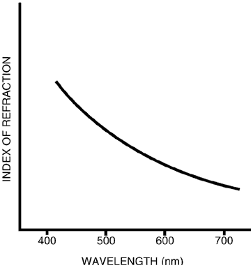
All spectacle lens materials exhibit dispersion, the variation of index of refraction with wavelength (Fig. 1). Index of refraction is highest for shorter (blue) wavelengths and lowest for longer (red) wavelengths. The ophthalmic industry quantifies the dispersion of a lens material using the Abbe number or Þgn value, defined as follows3:

Fig. 1. Dispersion curve for a hypothetical spectacle lens material.

(1)

Abbe number = nd - 1nf - nc

where nd is the index of refraction of the lens material for light of wavelength 587.56 nm, nf is the index for a wavelength of 486.13 nm, and nc is the index for a wavelength of 656.27 nm. Materials with higher Abbe numbers have less dispersion and are less likely to cause problems with chromatic aberration. As a general rule, the Abbe number tends to decrease as index of refraction increases, so materials of higher index have more dispersion than lower index materials (see Table 1).

CR-39 plastic and ophthalmic crown glass have the highest Abbe numbers of all lens materials. Problems with transverse chromatic aberration are rare for these materials.

Transmittance and Reflectance

The amount of light transmitted through a lens depends on the reflectance at each surface and on the amount of light absorbed by the material. Neither CR-39 plastic nor crown glass has any appreciable absorption of visible light, so all transmittance losses are by reflection. Reflectance from the lens surfaces is a function of index of refraction; the higher the index, the higher the reflectance. CR-39 plastic and crown glass have similar indices so reflections are similar in magnitude. A clear crown glass lens reflects 4.3% of the incident light at each surface and transmits 91.6% through the lens. A CR-39 plastic lens reflects 4.0% at each surface and transmits 92%. For practical purposes, the reflections and transmittances for the two materials are the same.

Fogging

Fogging is a problem that all spectacle wearers encounter in the winter. After a prolonged exposure to cold air, the lenses immediately “steam up” or fog when brought into a warm, humid room. Fogging occurs when the temperature of the lenses is lower than the dew point of the inside air. There is condensation on any article under these conditions.

The widespread belief that plastic lenses resist fogging better than glass is erroneous. Neither logic nor experiment supports it. CR-39 and other plastics have a lower thermal conductivity than glass. When the fog forms, it clears more slowly from plastic than from glass because the lens warms more slowly. For very brief encounters with cold air, plastic could have the advantage because it does not have time to cool below the critical temperature. Regardless, the differences in fogging are too slight to be a criterion for decision except in unusual cases, for example, lenses for a butcher who makes brief excursions into a refrigerated room. Even then, tests run with sample lenses should be made.

Antifog coatings are available, and some of them are quite effective. They function by making the lens surfaces more wettable so that condensed moisture forms a thin film of water rather than minute droplets. This film detracts from the patient's vision far less than droplets. The patient may not even be aware of the presence of the film. When the lens warms up, the film evaporates. Antifog coatings should not be used on lenses with antireflective coatings because the coating reflects light, defeating the purpose of the antireflective coating.4

Abrasion Resistance

CR-39 plastic lenses are much less abrasion resistant than crown glass. However, most patients do not have problems if the lenses are given proper care. Patients should be instructed to clean their lenses under a running stream of water, then to dry them with a soft, clean cloth or facial tissue. Paper towels are not a good alternative. The silica dust that accumulates on cloth or clothing exposed to the air will abrade a lens, so it is not a good idea to clean a plastic lens with a shirttail or the end of a tie. Even with the best of care, small scratches will occur on CR-39 plastic lenses, but these do not affect visual performance.

The perception of decreased abrasion resistance of CR-39 plastic lenses has led to the greatly increased use of abrasion-resistant coatings. In some markets, abrasion-resistant coatings are used on most lenses and are considered to be a basic necessity. Finished uncut lenses are commonly coated on both surfaces, whereas semifinished lenses are usually coated only on the front because the lens back surface is in a protected position and is not commonly scratched. A difficulty with scratch-resistant coatings is that, although they are hard, they are also thin. If a lens is accidentally slid across a desk top, it is likely to encounter a silica dust particle and the coating may be penetrated. A good abrasion-resistant coating can withstand regular cleaning with a cloth, but a grain of sand or sharp dust particle in the area being cleaned will scratch through the coating and leave a mark. Coated lenses should be cleaned with running water in the same manner as uncoated lenses.

Abrasion-resistant coatings can decrease the tintability of plastic lenses. As a general rule, hard abrasion-resistant coatings that are the most difficult to scratch do not tint as well as softer coatings.

HIGH-INDEX PLASTICS

High-index plastic lens materials have indices of refraction that are higher than the index of CR-39 plastic or ophthalmic crown glass. Current available indices range from 1.54 to 1.67 (see Table 1), but research continues on materials of even higher index. The weight of a high-index plastic lens will probably also be reduced relative to CR-39 plastic.

The radius of curvature of a surface of a lens is related to its power by:

(2)

D = n2 - n1r

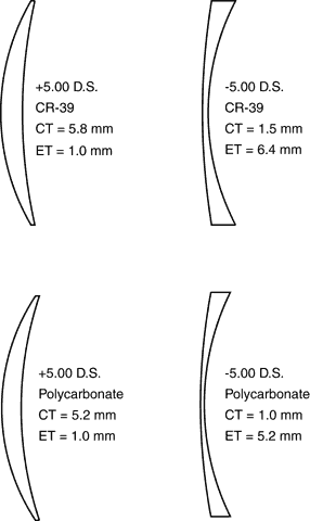
where n1 and n2 are the indices of refraction before and after refraction at the surface, respectively, r is the radius of curvature of the surface, measured in meters, and D is the surface power in diopters. The difference in radius of curvature between the front and back surfaces is relatively large for a lens made from a low-index material such as CR-39 or crown glass. Because the radii differ, there must be a relatively large difference between the center thickness and the edge thickness of the lens. High-index materials decrease thickness by decreasing the difference in radii between the two lens surfaces. The edge thickness of a minus-power lens or the center thickness of a plus-power lens (above the minimum center thickness value) is inversely related to its index of refraction.

Figure 2 shows cross-sectional views of CR-39 plastic and polycarbonate lenses of powers + 5.00 D and -5.00 D. The center thickness of the + 5.00-D polycarbonate lens is 10% less than that of the CR-39 plastic lens of the same power. The edge thickness of the -5.00-D polycarbonate lens is 19% less than that of the CR-39 plastic lens of the same power. Aspheric lens designs can provide additional decreases in thickness.

Fig. 2. Cross-sectional views of CR-39 plastic and polycarbonate lenses of power + 5.00 D and -5.00 D. Lenses are 60 mm in diameter. The minus-power polycarbonate lens has a thinner center than the CR-39 lens of the same power.

Polycarbonate, with a market share of approximately 23% of domestic lens shipments by U.S. manufacturers,1 is by far the most commonly used of the high-index plastics. There are many reasons for this, the most important of which is the tremendous impact resistance of polycarbonate plastic. There is no other material that should be substituted for polycarbonate when eye protection is a concern. Second, polycarbonate is less expensive than most other high-index plastics. Polycarbonate has been available for a longer time than most other high-index plastics and has a larger share of the ophthalmic lens market. With increased volume has come decreased cost. Third, polycarbonate is available in most lens types, including single-vision, aspheric, bifocal, trifocal, and progressive addition lenses. Again, this reflects the large market share of polycarbonate. Dispensers are more likely to use materials that they can obtain easily from their optical laboratory.

High-index plastics other than polycarbonate continue to increase in market share. The most commonly used are probably the 1.60 and 1.54 plastics, and the trend is toward increased use of the highest index materials that provide the thinnest, lightest lenses. Some high-index materials have less transverse chromatic aberration than polycarbonate. Most also require a smaller financial investment than polycarbonate and can be surfaced and edged in a manner similar to that of CR-39 plastic. Polycarbonate must be molded in very large presses under pressures of several thousand pounds per square inch for the more common prescriptions, and surfacing and edging often require special procedures. A manufacturer wanting to enter the high-index lens market can do so much more cheaply with a high-index material other than polycarbonate.

Thickness Considerations

In an effort to provide the thinnest lenses possible to the consumer, most manufacturers of high-index plastic lenses offer minus-power lenses in 1-mm center thicknesses. These lenses can be among the thinnest and lightest on the market, yet still meet U.S. Food and Drug Administration (FDA) impact resistance requirements. However, a 1-mm center thickness lens should be used with caution because it usually is less impact resistant than a thicker lens. In addition, a thinner lens may be more readily dislodged from a spectacle frame than a thicker lens,5,6 possibly causing an eye injury even if the lens does not break. When edge thickness is a critical concern for a minus-power lens, a shallow curve aspheric design with a 1.5-mm center thickness can provide an edge thickness similar to that of a spherical design with a 1-mm center thickness but with improved impact resistance. Polycarbonate with a center thickness of either 2 or 3 mm is best when impact resistance is a significant concern.

Abrasion Resistance

Most, but not all, high-index plastic materials have abrasion-resistant coatings. Polycarbonate plastic is inherently very soft, and its surfaces scratch easily. For this reason all finished polycarbonate lenses are supplied with abrasion resistant coatings on both surfaces. On semifinished polycarbonate lenses, the front surface is coated at the factory and the inside surface at the optical laboratory after surfacing. It is difficult to compare materials for abrasion resistance because some manufacturers may sacrifice abrasion resistance to improve tintability.

Transmittance and Reflectance

High-index plastic lenses reflect more light at each surface and therefore have a slightly lower transmittance than lenses of lower index. Whereas 4% of incident light is reflected at each surface of a CR-39 plastic lens, 5.3% is reflected at each surface of a lens of index 1.60. The abrasion-resistant coatings applied to some high-index plastic lenses may have antireflective properties. Some coated lenses actually may reflect less light than an uncoated CR-39 plastic lens.

Many high-index plastics have a slight inherent tint, often either grayish, greenish, or grayish-blue. This tint has no effect on the optical properties of the lenses and is a minor cosmetic concern. The tint does not allow a high-index lens to be identified by index or manufacturer. At one time, polycarbonate could be differentiated from other high-index plastics by the characteristic sound that a polycarbonate lens made when dropped onto a surface. However, other high-index plastics now sound similar and thus, the method is no longer reliable. The best indication that a lens is made of a high-index material is that the lens is thinner than expected. Some manufacturers have begun to mark their lenses with semivisible permanent identification marks similar to those of progressive addition lenses.

Generally, the high-index plastics, including polycarbonate, absorb all ultraviolet radiation below 380 nm. Unlike crown glass or CR-39 plastic, high-index plastic lenses do not have to be specially ordered, tinted, or coated to achieve this.

Impact Resistance

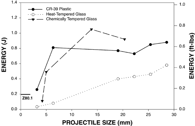
The impact resistance of polycarbonate is immensely superior to that of all other lens materials. It was this impact resistance that was the original motive for its use for ophthalmic lenses. The impact resistance of other high-index plastics is more comparable to that of CR-39 plastic. Impact resistance is covered in detail in a later section.

Color Aberrations

All the high-index plastics have lower Abbe numbers and more dispersion than either crown glass or CR-39 plastic. Dispersion results in transverse chromatic aberration when a patient looks away from the center of a high-power, high-index lens, but transverse chromatic aberration is usually a concern only for lenses of power greater than 5.00 to 6.00 D. Even so, many patients are willing to tolerate a few color aberrations as a trade-off for the decreased weight, thickness, and greatly improved cosmetic appearance of their high-index plastic lenses. In general, the lowest Abbe numbers correspond to the materials with the highest indices, so transverse chromatic aberration is more of a problem for these materials than for materials of lower index.

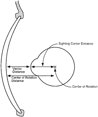
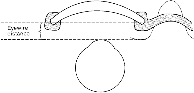
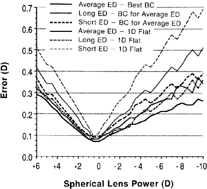
Differences between lens designs influence the off-axis optical quality of high-index plastics and may be just as important as differences in Abbe number. Some high-index plastic lens designs are not well documented. A poorly designed lens series with an intermediate Abbe number may perform worse than a well-designed series made from a material with a lower Abbe number, such as polycarbonate. Designs keyed to eyewire distances or fitting distance are recommended, especially for higher lens powers. Eyewire distance influences the choice of base curve for a given prescription more than any other single variable, and eyewire distance should be taken into account when choosing base curves, although not all manufacturers provide the information needed. Some lens designs have a limited base curve selection. Selection of base curve based on eyewire distance is described subsequently.

Other Considerations

A small, round frame is always best for high-index plastic materials because the small frame results in lenses that are as thin and light as possible. High-power lenses with larger amounts of transverse chromatic aberration should be positioned in the frame so that the optic axis of each lens passes through the center of rotation of the eye. This requires that the optical centers of the lenses be horizontally positioned using split interpupillary distances as measured with a pupillometer. Vertically, the optical center of each lens should be positioned 1 mm below the pupil center for every 2 degrees of panto-scopic tilt of the frame. Most frames have 6 to 10 degrees of tilt, so the optical center should be 3 to 5 mm below the center of the pupil. Most conservative frames naturally fit close to this position.

Back to Top
GLASS LENS MATERIALS

OPHTHALMIC CROWN GLASS

Ophthalmic crown glass is the standard glass lens material. Its low index of refraction and relatively high density results in thick, heavy lenses at high powers, and its usage has decreased greatly.

HIGH-INDEX GLASS

A number of high-index glass lens materials exist, although none are commonly used. Most contain oxides of heavy metals such as titanium, lanthanum, or niobium as additives to increase the index of refraction. However, these high-index glass materials are also more dense than crown glass and have lower Abbe numbers (see Table 1). The increased index of refraction decreases lens thickness, but the increased density tends to offset any weight advantage relative to crown glass. High-power lenses made of high-index glass are usually too heavy for comfortable wear unless the frame is fitted carefully to the patient's nose and ears. The decreased Abbe number requires that transverse chromatic aberration be considered for higher powers.

Probably the most commonly prescribed of the high-index glass lens materials is the titanium glass High-Lite, with index of refraction 1.701. Indices up to 1.90 are available, but as a general rule, glass with an index of refraction greater than 1.80 cannot be tempered to meet FDA impact resistance requirements. This characteristic limits their use. Whenever a lens that does not meet impact resistance requirements is prescribed, the patient must be notified in writing that the lenses are not impact resistant. Because of liability considerations, it is difficult to ever justify prescribing a nonimpact-resistant material purely for cosmetic reasons (i.e., to make the lenses thinner). The use of these extremely high-index materials cannot be recommended.

Flint glass is an older type of high-index glass made by adding lead oxides to the basic glass mixture. It is used only for such applications as x-ray protection for technicians in a hospital setting. Flint glass cannot be tempered to increase its impact resistance to acceptable levels. When flint glass is prescribed, the patient must be notified in writing that the lenses are not impact resistant.

Back to Top
HIGH-INDEX MATERIALS AND CUSTOM DESIGN
High-index materials have more dispersion and therefore more transverse chromatic aberration than either crown glass or CR-39 plastic. The amount of transverse chromatic aberration at a particular point on a lens can be calculated from7:

(3)

transverse chromatic aberration = h × DÞgn

where h is the distance of the point from the optical center of the lens in centimeters, D is the lens power in diopters, and Þgn is the Abbe number. Transverse chromatic aberration has units of prism diopters because the term h × D is Prentice's rule, the formula for calculating the amount of prism at any point on a lens. Equation 3 shows that transverse chromatic aberration is larger for lenses of higher powers, for larger viewing angles or larger distances from the lens optical center, and for materials with smaller Abbe numbers, which are primarily the higher index materials.

Both theoretical and experimental studies of transverse chromatic aberration suggest that the threshold for its detection is approximately 0.10 prism diopters.8,9 With this information, the lens power at which transverse chromatic aberration should be detectable can be calculated from equation 3. Polycarbonate, a high-index material with an Abbe number of 30, can be used as an example. At a distance of 1.5 cm (approximately 30 degrees) from the optic axis, the threshold of 0.10 prism diopters of transverse chromatic aberration is reached for a lens power of 2.00 D. However, clinical experience suggests that patients usually do not report problems caused by the chromatic aberrations of polycarbonate for lens powers less than approximately 5.00 D. For those patients who do, the problem is usually eliminated with proper choice of base curve.

The difference between theory and clinical experience is probably related to the differential effects of transverse chromatic aberration on high- and low-contrast targets. When a high-contrast target is viewed through a lens with transverse chromatic aberration, the color fringes only blur the target in one meridian, with other meridians relatively unaffected. At high contrast, this blur might not be expected to have much effect on visual acuity because the other meridians are still in focus. However, in low-contrast situations, transverse chromatic aberration may be more of a problem because even the unaffected target meridians are difficult to resolve. In other words, transverse chromatic aberration lowers the retinal image contrast in both the high- and low-contrast situations, but the contrast loss in the low-contrast situation may be more critical for visual resolution.

The off-axis monochromatic aberrations of a spectacle lens increase as lens power increases, even with the best possible base curve choice. At low powers, the aberrations have little effect on image quality, but the aberrations of higher power lenses may decrease off-axis image contrast enough that the total loss of contrast is significant. Use of the wrong base curve makes the problem even worse. Therefore, a proper base curve selection is of considerable importance for high-power, high-index lenses. Lens designers can make two modifications to standard lens design theory to optimize the base curve selection process for these lenses: (1) the use of smaller steps between base curves, approximately 1.00 D instead of the normal 2.00 D, resulting in more base curves for the available prescription range, with each base curve used for a smaller range of prescriptions, and (2) the use of different base curves for different lens positions on the face. The effects of vertex distance on lens performance are equally as important as the effects of base curve changes. Selection of the base curve of a lens based on the fit of the frame on the patient's face is termed custom design.

THE EYEWIRE DISTANCE

The distance from the back surface of a spectacle lens to the center of rotation of the eye is the center of rotation distance or stop distance. This distance is the sum of the vertex distance, the distance from the back surface of the lens to the apex of the cornea, and the sighting center distance, the distance from the corneal apex to the center of rotation of the eye (Fig. 3). The center of rotation distance has often been assumed to be a constant during the lens design process.10 However, at least four problems occur with this approach. The obvious one is that there may be considerable variation in stop distances in the general population. Second, the center of rotation distance changes as the base curve of a lens is steepened or flattened in the lens design process. Third, the vertex distance cannot be measured in the optical dispensary when preparing the order for spectacles because the new lenses for the patient's new frame are not yet available. Fourth, if a lens series is said to be designed for a given center of rotation distance, it is difficult for a clinician to relate that distance to the needs of a particular patient. A solution to these problems is to use eyewire distance.

Fig. 3. The center of rotation distance is the sum of the vertex distance and the sighting center distance.

The eyewire distance (Fig. 4) is the distance from the corneal apex to the plane of the nasal edge of the lens bevel; that is, to the eyewire groove of the frame at the nasal side. This measurement can be made easily in the optical dispensary, greatly reducing the uncertainty regarding the location of the center of rotation with respect to the spectacle plane. The eyewire distance is substantially the same as the nasal inset distance, the distance from the closest approach of the front edge of the nose to the plane of the corneal apices. Fry11 found the nasal inset distance to be 13.6 mm on average, with a standard deviation of 4 mm. Other unpublished surveys show a wide distribution of eyewire distances, from approximately 8 to 18 mm.

Fig. 4. The eyewire distance is the distance from the frame eyewire groove to the apex of the cornea. It differs from the vertex distance by the curvature of the back surface of the lens. (Modified from Davis JK: Prescribing for visibility. Probl Optom 2:131, 1990.)

The other important parameter needed to determine the center of rotation distance is the sighting center distance. Measurement of this distance has been the subject of considerable study. The average value for a plano prescription is 14.25 mm,12,13 but the distance is longer for myopes and shorter for hyperopes. The variation is small when compared with the variation in eyewire distances.

For lens design, a computer program can be written to calculate the center of rotation distance for a given refractive error, given the eyewire distance and base curve of the lens.

The effects of eyewire distance on the off-axis performance of a series of polycarbonate lenses is shown in Figure 5. For each power of lens, the optimal base curve was determined at a viewing angle of 30 degrees for an average eyewire distance of 13.6 mm. The residual off-axis error for this base curve was then calculated. Error was defined as the larger of either the plus meridional (tangential or sagittal) error or the radial astigmatism. A lens with an optimal base curve still has some error because it is not possible to correct both power error and radial astigmatism at the same time. Errors then were recalculated for the same lenses (with the same base curves), but for eyewire distances that were 4 mm longer or 4 mm shorter than optimal. For comparison, errors also were calculated at these three different eyewire distances for a base curve 1.00 D flatter than optimal. The figure shows that fitting a lens 4 mm too close or too far from the eye increases the off-axis error significantly. The increase is approximately one half that caused by flattening the base curve by 1.00 D, so it can be stated that a 4-mm fitting position error causes off-axis errors similar to a 0.50-D error in base curve choice. For stronger prescriptions, the sensitivity to fitting distance is even greater. Obviously, eyewire distance is an important parameter in lens performance.

Fig. 5. Error at 30 degrees off-axis for spherical power polycarbonate lenses. The heavy solid line shows the residual error for optimally designed lenses at an average eyewire distance. Other plots are errors for eyewire distances 4 mm longer or shorter than the design values and errors for the same eyewire distances, but with base curves 1.00 D flatter than ideal. Flattening the base curve by 1.00 D actually improves the off-axis performance of the lens fit 4 mm too far from the eye.

BASE CURVE SELECTION USING EYEWIRE DISTANCE

Custom base curve selection charts based on eyewire distance for semifinished polycarbonate lenses are available from Gentex Optics (Dudley, MA) by special request from the Optical Technology Group. Possibly other manufacturers may supply such charts. Gentex Optics also uses custom charts for their semifinished aspheric products. The Gentex Optics charts are for average (13.6 mm), long (17.6 mm), and short (9.6 mm) eyewire distances. It is unfortunate that truly high-quality lenses are not readily available for patients with strong prescriptions and unusual fitting dimensions. These patients would benefit significantly from the use of custom design.

Tables 2, 3, and 4 are custom base curve charts keyed to the eyewire distance. These tables can be used as a guide for selection of base curves for spectacle prescriptions and to verify that lenses supplied by an optical laboratory were made with the proper base curves. The tables were designed for an average index of refraction of 1.55, and they can be used for any material with an index between 1.50 (CR-39 plastic) and 1.60, including polycarbonate. A change in the index of refraction has far less effect on off-axis image quality than does a change in the eyewire distance. This makes possible one chart for the selected index range. Three eyewire range charts are necessary to keep significant off-axis errors to a minimum for stronger prescriptions. Custom design may not be as necessary for CR-39 plastic or crown glass because of their low dispersion. However, custom design still can improve the field of view for those patients with strong prescriptions and unusual fitting distances.


TABLE 2. Upper and Lower Base Curve Limits for Best Off-Axis Image Quality*


Cylinder0.00-0.50-1.00-1.50-2.00-2.50-3.00
Sphere       
7.0012.3512.3512.3512.3512.3512.3512.35
 11.3311.3311.3311.3311.3311.3311.33
 0.400.440.480.520.560.590.62
6.0012.2312.0312.2312.4412.6412.6412.64
 10.3310.3310.3310.3310.5510.5510.55
 0.360.400.430.470.510.540.57
5.0011.0411.0411.2611.4712.1112.7412.74
 9.519.519.519.519.519.519.51
 0.320.350.390.420.450.480.51
4.0010.2410.2410.4611.1211.5511.9811.98
 8.448.448.448.678.678.678.67
 0.270.300.340.360.390.420.44
3.009.399.629.8510.3010.7511.1911.19
 7.567.567.567.567.797.797.79
 0.220.250.280.310.330.360.38
2.008.768.999.459.9110.3710.3710.37
 6.426.426.426.666.666.666.89
 0.180.200.230.250.270.290.31
1.008.579.279.519.519.519.519.51
 4.794.795.035.035.265.035.03
 0.130.150.170.200.220.260.29
0.008.628.628.628.628.628.147.19
 2.402.884.324.564.564.324.32
 0.090.130.170.220.250.290.32
-1.007.907.907.907.666.956.475.99
 4.084.324.324.324.324.083.84
 0.120.170.210.250.280.320.35
-2.007.196.716.475.995.765.285.04
 4.324.324.084.083.843.603.36
 0.170.200.250.280.320.350.38
-3.005.995.765.285.044.804.564.32
 4.084.083.843.603.363.123.12
 0.210.250.280.320.340.380.41
-4.005.044.804.564.324.083.843.60
 3.603.603.363.123.122.882.64
 0.260.280.310.340.370.410.43
-5.004.324.083.843.603.603.363.12
 3.363.123.122.882.642.402.40
 0.280.310.340.370.410.430.45
-6.003.843.603.363.123.122.882.64
 3.122.642.642.402.402.162.16
 0.310.370.390.410.440.480.50
-7.003.363.122.882.882.642.402.40
 2.642.402.402.161.921.921.68
 0.340.390.410.480.480.510.55
-8.002.882.642.642.402.402.162.16
 2.162.161.921.921.681.681.44
 0.400.410.480.480.550.550.61
-9.002.402.402.162.161.921.921.68
 1.921.681.681.441.441.201.20
 0.400.470.470.540.540.590.60
-10.001.921.921.921.681.681.681.44
 1.441.441.201.201.200.960.96
 0.411.450.520.520.560.620.62

*Eyewire distance range is 7.1–12.1 mm (short). The third row or bottom row associated with each sphere power lists the largest error in diopters at a 30-degree viewing angle for the base curve range. This table may be used for CR-39 plastic, high-index materials up to index 1.60m and for the polycarbonate. The design refractive index was 1.55. Base curves for the lens powers between those listed in the table can be interpolated.


TABLE 3. Upper and Lower Base Curve Limits for Best Off-Axis Image Quality*


Cylinder0.00-0.50-1.00-1.50-2.00-2.50-3.00
Sphere       
7.0010.9110.9110.9110.9110.9110.9110.91
 10.2710.2710.2710.2710.2710.2710.27
 0.470.520.570.610.660.700.74
6.0010.9810.9810.9810.9810.9810.9810.98
 9.689.689.689.909.909.909.90
 0.340.380.420.460.500.530.56
5.0010.6110.6111.0411.2611.2611.2611.26
 8.628.858.858.858.858.858.85
 0.310.350.380.420.450.480.50
4.009.579.5710.0110.9011.5511.5511.55
 7.767.767.767.767.987.987.98
 0.270.300.330.360.390.420.44
3.008.718.949.399.8510.5211.1911.19
 6.876.876.876.876.877.107.10
 0.220.250.280.310.330.350.37
2.008.068.298.769.4510.3710.3710.37
 5.725.725.725.955.955.956.19
 0.170.200.220.250.270.290.30
1.007.878.809.519.519.519.278.34
 4.074.314.314.554.554.314.07
 0.130.150.170.190.220.250.29
0.008.628.628.628.627.666.715.99
 2.402.403.363.603.603.603.36
 0.090.130.170.210.250.280.31
-1.007.907.906.956.235.525.284.80
 3.363.603.603.363.363.122.88
 0.120.170.200.240.280.310.34
-2.005.995.525.284.804.564.083.84
 3.603.363.123.122.882.642.64
 0.160.200.240.270.300.330.35
-3.004.804.564.323.843.603.363.12
 3.123.122.882.642.402.402.16
 0.210.240.270.300.330.350.37
-4.003.843.843.603.363.122.882.64
 2.882.642.402.402.161.921.92
 0.230.270.300.320.350.390.40
-5.003.363.123.122.882.642.402.16
 2.402.402.161.921.921.681.68
 0.260.300.340.360.390.440.45
-6.002.882.642.402.402.162.161.92
 2.161.921.921.681.441.201.44
 0.290.350.360.430.430.500.50
-7.002.402.162.161.921.921.681.68
 1.681.681.441.441.201.200.96
 0.350.360.420.430.490.490.54
-8.001.921.921.681.681.441.441.44
 1.441.201.200.960.960.960.72
 0.350.410.410.470.480.520.57
-9.001.681.441.441.441.201.201.20
 0.960.960.960.720.720.720.48
 0.400.390.440.510.490.530.58
-10.001.201.201.200.960.960.960.96
 0.720.720.480.720.480.480.48
 0.360.400.460.460.490.530.57

*Eyewire distance range is 12.2–17.2 mm (average). The third row or bottom row associated with each sphere power lists the largest error in diopters at a 30-degree viewing anglefor the base curve range. This table may be used for CR-39 plastic, high-index materials up to index 1.60, and for polycarbonate. The design refractive index was 1.55. Base curves for lens powers between those listed in the table can be interpolated.


TABLE 4. Upper and Lower Base Curve Limits for Best Off-Axis Image Quality*


Cylinder0.000.501.001.502.002.503.00
Sphere       
7.009.849.849.849.849.849.849.84
 9.209.209.209.209.209.209.20
 0.640.690.740.790.840.890.93
6.009.689.689.689.689.689.689.68
 9.029.029.029.029.029.029.02
 0.400.440.490.530.570.610.64
5.009.739.739.739.739.739.739.73
 8.178.178.408.408.408.408.40
 0.300.340.370.410.450.470.50
4.009.129.1210.0110.2410.2410.2410.24
 7.307.307.307.307.307.307.53
 0.260.290.330.360.390.410.44
3.008.028.488.949.8510.5210.5210.52
 6.176.406.406.406.406.406.40
 0.210.250.280.300.330.350.37
2.007.367.838.529.4510.3710.3710.37
 5.255.255.255.255.485.485.48
 0.170.200.230.250.270.290.30
1.007.398.809.519.519.518.107.16
 3.603.834.074.074.073.833.60
 0.130.150.170.190.220.260.29
0.008.628.628.627.906.475.525.04
 2.402.402.882.882.882.882.64
 0.090.130.170.210.240.280.30
1.007.906.715.765.044.564.083.84
 2.882.882.882.642.642.402.16
 0.120.160.200.240.270.290.32
2.005.044.564.323.843.603.122.88
 2.882.642.642.402.162.161.92
 0.160.200.230.260.290.310.33
3.003.843.603.363.122.882.642.40
 2.642.402.161.921.921.681.68
 0.190.230.260.290.310.350.36
4.003.122.882.642.642.402.161.92
 2.161.921.921.681.681.441.44
 0.220.260.290.330.350.380.40
5.002.642.402.162.161.921.681.68
 1.921.681.441.441.201.200.96
 0.250.310.330.350.400.410.46
6.002.161.921.921.681.681.441.44
 1.441.441.201.200.960.960.72
 0.310.320.390.390.450.450.50
7.001.681.681.441.441.201.201.20
 1.200.960.960.720.720.720.48
 0.310.380.370.430.440.480.53
8.001.441.201.201.200.960.960.96
 0.720.720.720.480.480.480.48
 0.360.350.400.460.450.480.53
9.000.960.960.960.960.720.720.72
 0.480.480.480.480.480.480.48
 0.320.360.410.470.440.470.52
10.000.720.720.720.720.720.720.72
 0.480.480.480.480.480.480.48
 0.320.350.400.440.480.520.57

*Eyewire distance range is 17.3–22.3 mm (average). The third row or bottom row associated with each sphere power lists the largest error in diopters at a 30-degree viewing angle for the base curve range. This table may be used for CR-39 plastic, high-index materials up to index 1.60, and for polycarbonate. The design refractive index was 1.55. Base curves for lens powers between those listed in the table can be interpolated


The data in Tables 2, 3, and 4 are based on a study of more than 400 subjects, undertaken by the authors in 1996.14 This study found a slight difference in eyewire distance values from previous reports, with a mean eyewire distance of 14.7 mm and a standard deviation of 3.5 mm. There were slight differences among different racial groups, but of most importance was the large range of eyewire distance values found. The off-axis vision of patients with prescriptions above ±2.00 D and with eyewire distances far from the average could be significantly improved with custom design.

The base curve selection tables are based on three ranges of eyewire distances, 7.1 to 12.1 mm, 12.2 to 17.2 mm, and 17.3 to 22.3 mm. In the calculation process, the off-axis errors for the long and short eyewire distances of each range were balanced. The criterion for base curve selection was to minimize the largest tangential or sagittal meridional error or the astigmatism. There was no weighting of negative errors, which allows the charts to be applied to both presbyopic and nonpresbyopic patients. Once a best base curve for a given eyewire distance and prescription was found, the base curve was increased and decreased to find the limits at which the error increased by 0.08 D. The use of an index of refraction away from the design index of 1.55 would add a few hundredths of a diopter error to the 0.08-D value. With this range of base curves for each prescription, the optical laboratory may be able to stock a base curve within the range.

A third or bottom row of data has been added to each entry in the table. This row presents the calculated error in diopters at a 30-degree viewing angle for a base curve at the edge of the acceptable range. Choosing a base curve at the center of the range would reduce this value by 0.08 D.

An examination of the tables shows that for lens powers less than 2.00 D with small cylinders, a + 6.00-D base curve is acceptable. The acceptable base curve range is more narrow for minus-power lenses than for plus-power lenses, and strong minus-power lenses have the largest errors. Departure from the design choices in the tables increases these errors even further.

The following example illustrates the use of the tables. A polycarbonate lens of power -3.00 -1.50 × 170 is to be ordered for a patient, and an eyewire distance of 12 mm is measured. (If the prescription is written in plus-cylinder form, it must be transposed to minus-cylinder form before using the tables.) This eyewire distance value requires the use of Table 2. At the intersection of the -3.00-D sphere row and the -1.50-D cylinder column, the base curve range is 3.60 to 5.04. A base curve of 4.25 or 4.50, near the center of the range, would be a good choice. The off-axis error with either of these base curves would be less than 0.32 D, the third entry in the table.

These tables should be used with a knowledge of their limitations. When base curve charts keyed to eyewire distance are available from a manufacturer of a lens material, the charts provide a better design than the tables, but the tables ensure an acceptable design when manufacturers' data are not available. Base curve availability varies considerably with lens material and type. Some high-index plastics are available in a limited number of base curves, and custom design matching the requirements of the tables may not be possible. In general, multifocal lenses are available in fewer base curves than single-vision lenses.

If the base curve or eyewire distance is not specified when a spectacle prescription is ordered, laboratory personnel choose the base curve for the lens based on information supplied by a lens manufacturer or from a computer software package. This information is presumed to be based on average eyewire distances. Tables 2, 3, and 4 can be used to evaluate the laboratory's choice of base curve. Custom design should always be considered for high-power (greater than 3.00 D), high-index lenses when the fitting distance is unusual. Only for the weakest of prescriptions is custom design of no value.

Back to Top
IMPACT RESISTANCE AND EYE PROTECTION
Impact-resistant lenses may be divided into two classifications based on their function: impactresistant dress lenses (lenses to be worn for everyday use) and impact-resistant industrial protective lenses. Because most prescriptions written by ophthalmologists and optometrists are for dress eyewear, we devote most of our attention to the impact resistance of these lenses. Dress impact-resistant lenses are “ordinary” lenses. Practically speaking, there is no less safe lens available.

DRESS IMPACT RESISTANCE STANDARDS

Effective January 1, 1972, the FDA mandated that all dress ophthalmic lenses prescribed must be impact resistant. Impact resistance is a relative term; when used, it has a specific definition. Terms such as shatterproof, safety, or unbreakable should never be used because they are misleading.

To be considered impact resistant, a lens must pass the dress ophthalmic lens drop-ball test.3,15,16 The lens must be able to withstand the impact of a -
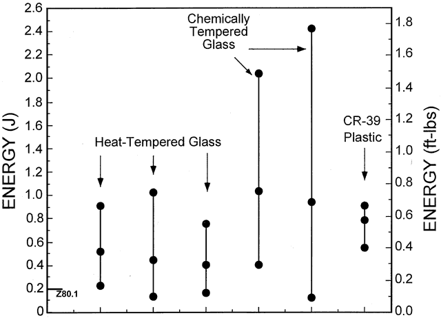
inch (15.875-mm) steel ball dropped from a height of 50 inches (1.27 m) onto the lens front surface. All prescription spectacle lenses must be tested individually, with some exceptions, and testing is performed before the lenses are placed in the frame. Some lenses, such as raised-ledge multifocal lenses and plastic lenses, which may be damaged by the drop-ball test, need not be tested individually if they have been properly fabricated by the optical laboratory and if statistical testing (batch testing) by the manufacturer demonstrates that the lenses will meet the test requirements. Special lens types, such as eikonic lenses, lenses containing slab-off prism, and prescription polarized laminated glass sunglass lenses, are exempted from testing, although these lens types still must be made of impactresistant materials. The ophthalmic practitioner also may waive testing for impact resistance, but the patient must be notified in writing. It is difficult to justify waiving the impact resistance requirement under any circumstance because of the potential for liability problems. One possible situation might be the use of flint glass for x-ray protection; another would be the need for replacement spectacles in an emergency when there is not time to temper the glass lenses.

Nonprescription sunglasses also must be impact resistant. Unlike prescription lenses, these lenses, whether glass or plastic, may be batch tested for impact resistance by the manufacturer.

The FDA further requires that the lens manufacturer, optical laboratory, ophthalmologist, optometrist, and optician all maintain records of impact resistance testing, copies of invoices, shipping documents, and bills of sale for at least 3 years. It is not necessary to maintain records of those purchasing nonprescription sunglasses or over-the-counter reading glasses at the retail level.

The FDA does not have a minimum thickness requirement for ophthalmic lenses. Lenses made from crown glass and CR-39 plastic will not reliably pass the drop-ball test unless they are at least 1.5 to 2 mm thick. Polycarbonate and some of the other high-index plastics can be made with center thicknesses as low as 1 mm in minus powers. Improvements in coating technology also allow thinner plastic lenses. One advance is the so-called primer coat, a rubber-like coating applied under the abrasion-resistant coating of a plastic lens. This coating acts as a shock absorber to disperse the energy of an impact, and it also acts to prevent a crack in the abrasion-resistant coating from propagating throughout the lens. With this technology, it is possible for essentially any minus-power plastic lens to be manufactured with a 1-mm center thickness.

SIGNIFICANCE OF THE DROP-BALL TEST

The FDA-mandated drop-ball test results in an impact energy of 0.2 joules (J) or 0.15 foot-pounds (ft-lb) on the lens front surface. Many simple accidents and sports missiles result in energies that exceed this value by anywhere from 2 to 100 times.

STRENGTHS OF LENS MATERIALS

The impact resistance of a lens is a function of the material from which it is made, any special treatment of the material, and the thickness, size, and shape of the lens. In addition, the method of support contributes to the strength of the mounted lens.

For dress eyewear prescriptions, the choice of frame is usually made independently of the lens type or material, and the lens thickness is maintained at the allowable minimum. Thus, the variables that affect the impact resistance of a lens are the material and any treatment of the material that may enhance or degrade its impact resistance.

Glass Lenses

The elementary structural units of glass are not molecules, crystals, or grains but are charged atoms (ions) that are arranged in a random amorphous relationship. The attraction between ions creates bonds that are inherently extremely strong. However, even the slightest imperfection in the surfaces, such as the abrasion caused by rubbing with paper or a small defect caused by rough handling, weakens a brittle material like glass. The abrading techniques used to surface glass spectacle lenses during the manufacturing process create minute flaws that interrupt the bonds near the surface and weaken it. The edging process also creates similar defects. Thus, a glass spectacle lens as it is commonly used has lost much of its inherent strength and requires treatment (tempering) before it can be considered impact resistant.

Because the strength of the lens surface is the determining factor in the strength of a glass lens, an obvious way to improve the strength of a lens would be to improve the strength of the surface. The surface has a certain tensile strength, and it is desirable not to put tension on the surface in excess of this strength. If a way could be found to compress the surface, then a force acting on the lens surface would need to overcome this compression before fracturing the lens. This is the mechanism of achieving lens strength for heat and chemical tempering.

HEAT TEMPERING. The heat tempering process consists of heating a lens almost to its softening point, then rapidly cooling the lens with jets of air. Heat tempering makes a dress lens approximately two to three times as impact resistant as an untreated lens, but a heat-tempered dress lens is not as impact resistant as a chemically tempered dress lens, nor is it as impact resistant as any other type of dress ophthalmic lens. For this reason, heat tempering cannot be recommended.

Heat tempering is still occasionally used for plano (nonprescription) industrial lenses and for some industrial prescription eyewear. One important reason is that a heat-tempered lens can be readily identified. Also, heat tempering works better for thicker industrial lenses than for dress lenses because there is room for a thick compression layer.

CHEMICAL TEMPERING. Chemical tempering uses a process of ion exchange to create a compressed surface layer in a lens. Crown glass lenses are immersed in a potassium nitrate bath at 450°C for 16 hours.17 Sodium ions from the glass migrate into the bath, and potassium ions migrate into the glass. The potassium ions are larger than the sodium ions they replace, crowding the ions in the lens surface and compressing it. The compression is much higher and more uniform than that obtained with heat tempering, resulting in greater impact resistance.18 Chemical tempering is the preferred method of treatment for dress glass lenses.

Glass photochromic lenses are chemically tempered by immersion for 16 hours in a bath that is a mixture of potassium nitrate and sodium nitrate at 400°C.17 A 2-hour chemical tempering process that uses a potassium nitrate bath is also available, but this process can only be used for dress photochromic lenses.19

The compression developed at the surfaces of a chemically tempered lens is higher than that for a heat-tempered lens, but the compression layer is thinner.20 A flaw or scratch that penetrates the compression zone severely weakens a lens,21,22 so the impact resistance of a chemically tempered lens is more vulnerable to compromise from a deep scratch.

IMPORTANCE OF GOOD LABORATORY PRACTICE. The process of tempering glass lenses imposes limits on the practice of lens modification. Before impact resistance treatment was available, lenses could be resurfaced to eliminate scratches or alter the prescription slightly. Often, the edging would be touched up so that the lens would fit into the frame more easily. None of these modifications can be undertaken with a glass lens that has been tempered because penetration of the compression zone weakens the lens. The lens may break during modification or be weakened such that any slight blow may result in fracture.

The sensitivity of tempered lenses to surface flaws also requires that optical laboratory personnel put proper safety bevels or “pin” bevels on a lens. These bevels are applied by hand after a lens has been edged. They are designed to remove the sharp corners at the junction of the lens surfaces and the lens bevel, and also to remove small chips created during the edging process. If these bevels are not properly applied, the lens may chip during insertion into the frame or during routine wear, compromising the impact resistance of the lens.

Tempering followed by the drop-ball test must be the last operation before a glass lens is mounted in a frame. If modification or touch-up is necessary, the lens must be retempered and retested before it is mounted.

An important problem with chemical tempering is the difficulty of identifying a chemically tempered lens. Glass that is in a state of compression or tension is birefringent or doubly refracting, a property that allows the glass to alter the polarization of light. If a light source is viewed through two polarizing filters with their axes of polarization 90 degrees apart (a polariscope), the field appears dark. When a heat-tempered lens is placed between the polarizers, birefringence alters the polarization and some light is transmitted, creating a light and dark pattern. A chemically tempered lens and an untempered annealed glass lens do not show a pattern because the compressive stresses are more uniform. Chemical tempering can be verified by immersing the lens edge in a liquid similar in index to that of the lens while viewing the lens edge through crossed polarizers.23 If the lens has been chemically tempered, the edge glows.

Plastic Lenses

The most common ophthalmic plastic, CR-39, has molecules that are long and fibrous, made up of chains of atoms. These molecules have branches and even cross-linkages between chains, so in effect, each lens is one big molecule. Most of the high-index plastics except polycarbonate have a similar structure. Lenses made from these materials are not tempered and usually pass the drop-ball test if manufactured to the proper thickness.

Polycarbonate Lenses

Polycarbonate is different from any other plastic. Its molecules are extremely long chains of atoms that can slide back and forth on each other. The result is a tough material that can be flexed and even deformed permanently without breaking. Thus, the energy of an impact will flex or deform the lens rather than break it. This property results in extremely high impact resistance relative to all other lens materials.

COMPARISONS OF MATERIALS

Figure 6 compares the impact resistance of heat-tempered glass, chemically tempered glass, and CR-39 plastic for large projectiles ( ,- and C· v-inch drop-balls) as compiled from a number of studies. Glass lenses show a much larger range of impact resistance values than does CR-39 plastic. This variability is most likely related to damage that occurs at the lens surfaces during surfacing and edging. It is more difficult to predict the impact resistance of glass than of plastic lenses. On average, chemically tempered glass is slightly more impact resistant than CR-39 plastic for a ,-inch steel ball, and both are more impact resistant than a heat-tempered dress lens. However, a given chemically tempered dress lens or heat-tempered dress lens can be much less impact resistant than a CR-39 plastic lens. Drop-ball testing “weeds out” the weakest tempered glass lenses, but weak glass lenses with just enough impact resistance to barely pass the drop-ball test will always be present.

Fig. 6. Average impact energies and range of impact energies that fracture 2-mm thick spectacle lenses. Projectiles were ,- or C· v-inch steel balls. Z80.1 indicates the impact energy of the ANSI dress lens drop-ball test, 0.2 J or 0.15 ft-lb. (Modified from Davis JK: Perspectives on impact resistance and polycarbonate lenses. Int Ophthalmol Clin 28:215, 1988.)

The relative impact resistance of lens materials varies with projectile size, as shown in Figure 7. Heat-tempered and chemically tempered glass perform poorly relative to CR-39 plastic for small projectiles, but chemically tempered glass is superior to CR-39 for larger projectiles. This difference is related to the differences in structure of the materials. Large, relatively slow-moving projectiles that may flex a glass lens and distribute the tension over a wide area are less likely to start a fracture than are small, high-speed projectiles of the same impact energy that concentrate the force locally and increase the size of a pre-existing flaw. Also, the inertia of the glass lens prevents it from reacting and flexing in response to a high-velocity, low-mass impact, increasing the stress at the area of impact. The long molecules of CR-39 plastic hold the lens together and prevent cracks from propagating when the lens is impacted by small, high-velocity projectiles that stress a small area. When hit by a large, slow-moving projectile, the CR-39 plastic lens flexes and often breaks at a flaw beginning in the lens edge. This transfer of stress to the lens edges during impact suggests that the impact resistance of CR-39 plastic lenses may depend on the quality of the edge that is put on the lens at the optical laboratory.

Fig. 7. Average impact energies fracturing 2-mm thick lenses as a function of projectile (steel-ball) diameter. Impact energy increases with both projectile size and projectile velocity. Z80.1 indicates the impact energy of the ANSI dress lens drop-ball test ( ,-inch steel ball). (Modified from Davis JK: Perspectives on impact resistance and polycarbonate lenses. Int Ophthalmol Clin 28:215, 1988.)

The breakage pattern of CR-39 plastic differs from that of glass. CR-39 plastic lenses tend to break into larger pieces than glass lenses when struck by both small and large projectiles.24–26 The relative merits of the various breakage patterns are subject to argument, but neither CR-39 plastic nor glass can provide the eye protection offered by polycarbonate.

The superior impact resistance of polycarbonate relative to all other lens materials has been demonstrated by a number of studies. Wigglesworth27 determined the impact resistance of 1.9-mm thick polycarbonate for 3.175-mm ( ,-inch) and 6.35-mm (Z· v-inch) steel balls. The impact energy needed to break polycarbonate was approximately 21 times that needed to break CR-39 plastic for the same projectile sizes. Greenberg and coworkers28 were able to break 3-mm thick polycarbonate lenses with 6.35-mm (Z· v-inch) steel balls traveling at an average velocity of 152 m/sec (500 ft/sec). CR-39 plastic lenses with a thickness of 3 mm broke at an average velocity of 45 m/sec (150 ft/sec), whereas heattempered crown glass of the same thickness broke at a velocity of 24 m/sec (80 ft/sec). Vinger and colleagues29 compared the impact resistance of CR-39 plastic, crown glass, polycarbonate and other high-index plastics. A 1-mm thick high-index plastic lens broke when struck by a tennis ball traveling at 17.8 m/sec (40 mph). Crown glass and CR-39 plastic lenses of various thicknesses broke at a velocity of 39.4 m/sec (89 mph) or less. Polycarbonate lenses of thickness 1 mm did not break when struck by a tennis ball traveling at the maximum velocity of the test equipment, approximately 68 m/sec (152 mph). All crown glass, CR-39 plastic, and high-index plastic lenses broke when struck by a baseball at the lowest velocity attempted, 42.2 m/sec (94 mph). A 1-mm thick polycarbonate lens broke when struck by a baseball at 51.7 m/sec (116 mph), but a 3.1-mm thick polycarbonate lens did not break when impacted by a baseball at the highest velocity tested, 60 m/sec, or 135 mph. Polycarbonate is the only material that should be used when eye protection is a concern.

The popularity of coatings for tints, abrasion resistance, and reduction of reflections has complicated the impact resistance picture, especially for the high-index plastics. Coatings tend to decrease the impact resistance of a lens,28,30 probably by putting a tensile stress on the lens back surface. At a 1-mm center thickness, a coated lens can still meet the requirements of the drop-ball test, but manufacturers generally warrant that their lenses are impact resistant at this thickness only if all lens manufacturing processes, including coatings, are performed by the manufacturer. For this reason, lenses with 1-mm center thicknesses in minus powers are commonly available from the manufacturer only as uncut or finished blanks. An optical laboratory using semifinished high-index lens blanks usually will not surface lenses thinner than 1.5 mm because of impact resistance considerations. The effects of coatings on impact resistance are not a concern with polycarbonate because of its great reserve of impact resistance. Polycarbonate is routinely surfaced by optical laboratories to a 1-mm center thickness in minus powers.

SPECTACLES AND EYE INJURIES

Which types of projectiles break spectacles and cause eye injuries in spectacle lens wearers? Probably the most comprehensive study was performed by Keeney and associates,31 who showed that in nonindustrial situations, most incidents of broken glasses and eye injuries were caused by relatively large, slow-moving objects (Table 5). Studies of eye injuries in children and in the general population, both with and without spectacles, show that eye injuries are caused by a wide variety of object sizes and velocities. A substantial percentage of the injuries are related to sports.32–34 Eye injuries in industry and in the military appear to be caused primarily by smaller, high-velocity projectiles.35–37


TABLE 5. Causes of Broken Spectacle Lenses*


CauseNo.%
Rocks7324.5
Sports5317.8
Basketball8 
Golf ball5 
Other balls8 
Fishing weights4 
Archery bow1 
Plastic hockey puck1 
Boomerang1 
Golf club1 
Auto crashes289.4
Falls258.4
Flying objects206.7
Assaults186.0
BB pellets165.4
Running collisions124.0
Tree branches72.3
Nails62.0
Exploding objects41.3
Tools (screwdriver, pliers, etc.)41.3
Auto and truck springs20.7
Corks20.7
Wrestling20.7
Miscellaneous (1 each)113.7
Unknown155.0
Total298100%

*Eye injuries occurred in 157 of the 298 cases/
(Modified from Keeney AH, Fintelmann E, Renaldo D: Clinical mechanisms in non-industrial eye trauma. Am J Ophthalmol 74:662, 1972. Published with permission from the American Journal Of Ophthalmology. Copyright The Opthalmic Publishing Company)


One of us (Davis) has been involved in litigation as an expert witness in many nonsport situations. For example, eye injuries have resulted from playfully tossed crab apples, plastic drinking glasses, and a fist in a bar doorway. An eye injury may have been caused by a tossed magazine. In automobile accidents, eye injuries result from broken spectacles and sunglasses, and some eye injuries have been caused by spectacles broken during airbag inflation.38 Many injuries result from falls and collisions with objects. The impact energies in most of these cases are far beyond what is needed to break CR-39 plastic and crown glass.

The minimum energy in foot-pounds at the receiving end of a thrown object is equal to the weight of the object in pounds multiplied by the distance in feet it is thrown divided by 2. A typical magazine weighing 12 ounces thrown 6 feet provides an impact energy of 2.25 ft-lb, or 3 J. This is 15 times the impact energy of the drop-ball test, easily enough to break CR-39 plastic or crown glass, but not 2-mm thick polycarbonate.

Because of the wide variety of projectile sizes and velocities associated with broken spectacle lenses and eye injuries, crown glass and CR-39 plastic cannot provide reliable protection against all objects. Only polycarbonate can resist the high-impact energies of both large and small objects. Whenever eye protection is a concern, for example, for industrial workers, for athletes, for children, and for monocular or amblyopic patients, only polycarbonate plastic provides adequate protection. In fact, one should have a reason when polycarbonate is not prescribed in these situations.

EYE PROTECTION IN INDUSTRY

The US Occupational Safety and Health Administration (OSHA) requires that all industrial eye and face protectors meet the requirements of ANSI Z87.1-1989—American National Standard Practice for Occupational and Educational Eye and Face Protection.39–41 Protectors covered by the standard include goggles, face shields, welding helmets, and both prescription and nonprescription spectacles. A discussion of the requirements for prescription eyewear follows.

For spectacles to be considered protective in industry, both the lenses and the frame must meet the ANSI Z87.1 standard. Industrial lenses in a dress frame or dress ophthalmic lenses in an industrial frame do not meet the standard and should never be prescribed or dispensed.

The following summarizes the current requirements for industrial prescription spectacle lenses:

  1. All lenses must be able to withstand the impact of a 1-inch (25.4-mm) steel ball dropped 50 inches (1.27 m) onto the lens front surface (the industrial drop-ball test). Lenses that might be damaged by the test (e.g. plastic lenses) are tested using an appropriate batch-testing protocol.
  2. All lenses must have a minimum thickness of 3 mm. Lenses of power greater than + 3.00 D in the more plus meridian can have a minimum thickness of 2.5 mm. A thickness requirement is one of the main differences between the dress and industrial eyewear standards.
  3. All lenses must be permanently marked with the monogram or trademark of the optical laboratory that provides the finished lenses.
  4. Tinted lenses are allowed, but they should be prescribed only with knowledge of the patient's lighting and working conditions. For example, sunglasses should not be prescribed for indoor use, for driving a vehicle with a tinted windshield, or for driving at night. Older patients with smaller pupils and decreased media transmittance are poor candidates for any type of tint. A tinted lens can be a protective filter (for use in welding and other potentially hazardous situations) only if the tint meets the ANSI Z87.1 standards for visible, ultraviolet, and infrared radiation transmittance. Sunglass tints usually do not meet these standards. Protective filters also have specific marking or labeling standards. Photochromic lenses are acceptable for use in industry except for situations in which their use might be hazardous. One example of a hazardous situation would be use of the lenses while driving a forklift from outdoors to indoors. The lenses do not lighten immediately, so visual performance could be compromised.
  5. Recommendations for prescription power accuracy are those of the ANSI Z80.1-1995 standard.3
  6. OSHA requires that side-shields be used whenever there is the potential for injury from flying objects,40,41 although this requirement is not part of the ANSI Z87.1 standard itself. Detachable side-shields are acceptable.

Industrial frames are identified by the marking Z87, which is stamped on the frame front and temple. These frames may be superficially similar in appearance to regular dress (nonindustrial) frames, but industrial frames must meet specific strength and durability requirements as described in the ANSI Z87.1 standard. Nonprescription protective eyewear is sold by opticians, sporting goods stores, and hardware stores. Patients should be advised to look for the Z87 label and to read instructions that describe the intended use of the protector.

Polycarbonate plastic is clearly the best lens material for prescription industrial eyewear. The decreased abrasion resistance of coated polycarbonate relative to crown glass should not be considered reason for prescribing glass unless the work environment includes severe conditions that warrants the use of glass lenses. The use of polycarbonate can be a problem in cold, dusty work environments because static charges cause dust to cling to the lenses.

LEGAL CONSIDERATIONS OF IMPACT RESISTANCE

An increased concern with liability from breakage of ophthalmic lenses has been attributed to the development of new lens materials and to the development of national standards that have become the basis for legal decisions.42 Some suggestions for minimizing or preventing materials liability follow43:

  1. Be familiar with the most recent ANSI Z80.1 and ANSI Z87.1 standards and FDA and OSHA requirements. A copy or summary of the Z80.1 standards should be available in the optical dispensary for reference. Both prescription and nonprescription sunglasses must meet the FDA standard for impact resistance.
  2. Remember that the most common cause of ophthalmic materials liability is failure to prescribe the proper lens material. Most problems occur when polycarbonate lenses are not prescribed when indicated. Patients for whom polycarbonate lenses are especially recommended include athletes, monocular patients or amblyopes, patients with hazardous occupations in which eye protection is not provided by the employer, patients with hobbies that require eye protection (such as carpentry or automobile refurbishing), and children. Also, sunglasses that are likely to be worn for sports activities should have polycarbonate lenses.
  3. Take careful case histories to determine special eye protection needs. Discuss the properties of polycarbonate with patients who have special needs. Consider special eye and face protectors for patients who are active in sports.
  4. When prescribing specially designed sports eye protectors, especially for racket sports, be sure that the protectors meet applicable standards.
  5. Maintain detailed records. When prescribing special lens materials, document this on both the record and the prescription form. If a patient refuses your advice, be sure to document the refusal.
  6. Avoid terms such as unbreakable, safety, and shatterproof. The preferred term is impact resistant. Never guarantee that lenses are unbreakable.
  7. Be certain that ancillary personnel are aware of considerations regarding impact resistance. Often, assistants and technicians are in a position to recommend lens materials and sports protectors to patients.
  8. If a manufacturer of frames or lenses provides a warning about a product, this warning should be passed along to the patient.
  9. Never place industrial lenses in a dress frame or dress lenses in an industrial frame. These spectacles do not meet the industrial standards.

Back to Top
REFERENCES

1. Optical Industry Association Report of Member Shipments, 3rd Quarter, Year to Date (Through September 1999). Arlington, VA: Optical Industry Association, 1999

2. Graham R: Plastic lenses made of thermosetting resins. Am J Optom Arch Am Acad Optom 26:358, 1949

3. American National Standard for Ophthalmics—Prescription Ophthalmic Lenses—Recommendations. ANSI Z80.1-1995. New York: American National Standards Institute, 1995

4. Young JM: AR coating: A definition. Optical World 17:8, 1988

5. Johnson YM, Good GW: Ophthalmic lens retention in safety frames. Optom Vis Sci 78:104, 1996

6. Vinger PF, Woods BA: Prescription safety eyewear: Impact studies of lens and frame failure. In Proceedings of the American Society of Safety Engineers, pp 445–463. Des Plaines, IL: ASSE Professional Development Conference and Exposition, 1999

7. Fannin TE, Grosvenor T: Clinical Optics, p 132. 2nd ed. Boston: Butterworth-Heinemann, 1996

8. Meslin D, Obrecht G: Effect of chromatic dispersion of a lens on visual acuity. Am J Optom Physiol Opt 65:25,1988

9. Davis JK, Clotar G: An approach to the problem of a corrected curve achromatic cataract lens. Am J Optom Arch Am Acad Optom 33:643, 1956

10. Davis JK: Geometric optics in ophthalmic lens design. Proc Soc PhotoOptical Instrum Engineers 39:65, 1973

11. Fry GA: Measurement of the splay and slope angles of the nose. O-Eye-O 15, 1959

12. Fry GA, Hill WW: The center of rotation of the eye. Am J Optom Arch Am Acad Optom 39:581, 1962

13. Grolman B: The sighting center. Am J Optom Arch Am Acad Optom 40:666, 1963

14. Stephens GL, Perrigin DM, Davis JK, Waido RP: Nasal eyewire distance, nasal inset distance, and ophthalmic lens design. Optom Vis Sci 73(Suppl):217, 1996

15. Use of Impact Resistant Lenses in Eyeglasses and Sunglasses. Code of Federal Regulations 21 CFR 801.410, Washington, DC: Office of the Federal Register, revised April 1, 1990

16. Impact Resistant Lenses: Questions and Answers. Rockville, MD: US Department of Health and Human Services, Food and Drug Administration, Bureau of Medical Devices, 1987

17. Chemtempering Lenses Made from Corning Glass Materials. Technical Bulletin OPO-367 CT, Corning, NY: Corning, 1996

18. Davis JK: Perspectives on impact resistance and polycarbonate lenses. Int Ophthalmol Clin 28:215, 1988

19. Two-hour chemtempering of Corning photochromic glasses. Corning Technical Bulletin, December 1990

20. Brandt NM: The anatomy and autopsy of an impact resistant lens. Am J Optom Physiol Opt 51:982, 1974

21. Peters HB: The fracture resistance of industrially damaged safety glass lenses. Am J Optom Arch Am Acad Optom 39:33, 1962

22. Silberstein IW: The fracture resistance of industrially damaged safety glass lenses, plano and prescription—An expanded study. Am J Optom Arch Am Acad Optom 41:199, 1964

23. Kirschen M: Verifying impact resistance. Optom Manage 13(9):55, 1977

24. Keeney AH: Lens Materials in the Prevention of Eye Injuries, p 57. Springfield, IL: Charles C. Thomas, 1957

25. Williams RL, Stewart GM: Ballistic studies in eye protection. Am J Ophthalmol 58:453, 1964

26. Newton AW: Industrial eye protection—An appraisal of some current safety lens materials. J Inst Eng Aust 39: 163, 1967

27. Wigglesworth EC: A comparative assessment of eye protective devices and a proposed system of acceptance testing and grading. Am J Optom Arch Am Acad Optom 49: 287, 1972

28. Greenberg I, Chase G, Lamarre D: Statistical protocol for impact testing prescription polycarbonate safety lenses. Optical World 14(March/April):7, 1985

29. Vinger PF, Parver L, Alfaro V et al: Shatter resistance of spectacle lenses. JAMA 277:142, 1997

30. Corzine JC, Greer RB, Bruess RD et al: Effects of coatings on the fracture resistance of ophthalmic lenses. Optom Vis Sci 73:8, 1996

31. Keeney AH, Fintelmann E, Renaldo D: Clinical mechanisms in non-industrial eye trauma. Am J Ophthalmol 74: 662, 1972

32. Karlson TA, Klein BEK: The incidence of acute hospital-treated eye injuries. Arch Ophthalmol 104:1473, 1986

33. Grin TR, Nelson LB, Jeffers JB: Eye injuries in childhood. Pediatrics 80:13, 1987

34. Nelson LB, Wilson TW, Jeffers JB: Eye injuries in childhood: demography, etiology, and prevention. Pediatrics 84:438, 1989

35. Wigglesworth EC: The impact resistance of eye protector lens materials. Am J Optom Arch Am Acad Optom 48: 245, 1971

36. Accidents Involving Eye Injuries. Report 587. Washington, DC: US Department of Labor, Bureau of Labor Statistics, April 1980

37. Hornblass A: Eye injuries in the military. Int Ophthalmol Clin 21(4):121, 1981

38. Gault JA, Vichnin MC, Jaeger EA, Jeffers JB: Ocular injuries associated with eyeglass wear and airbag inflation. J Trauma Injury Infect Crit Care 38:494, 1995

39. American National Standard Practice for Occupational and Educational Eye and Face Protection, ANSI Z87.1-1989. New York: American National Standards Institute, 1989

40. Occupational Safety and Health Administration, US Department of Labor: Personal protective equipment for general industry. 29 CFR Part 1910. Fed Register 59:16334, 1994

41. Occupational Safety and Health Administration, US Department of Labor: Personal protective equipment for general industry. 29 CFR Part 1910. Fed Register 59:34580, 1994

42. Classe JG: Clinicolegal aspects of practice. South J Optom 4:36, 1986

43. Stephens GL: Impact resistance. In Pitts DG, Kleinstein RN, (eds): Environmental Vision: Interaction of the Eye, Vision, and the Environment, pp 281–297. Boston: Butterworth-Heinemann, 1993

Back to Top