Chapter 44
Prescribing Multifocal Lenses
JAMES E. SHEEDY
Main Menu   Table Of Contents

Search

INTRODUCTION
HISTORY
SELECTING THE MULTIFOCAL FOR THE PATIENT
DETERMINING THE ADD
BIFOCALS
FITTING BIFOCAL LENSES
PROGRESSIVE ADDITION LENSES
OCCUPATIONAL PROGRESSIVE LENSES
ANISOMETROPIA—VERTICAL IMBALANCE AT NEAR
FUTURE OF MULTIFOCAL LENSES
REFERENCES

INTRODUCTION
Multifocal spectacle lenses are primarily used in the treatment of presbyopia. Secondary usages include treatment of esophoria and pre-presbyopic accommodative dysfunctions such as reduced accommodative amplitude or accommodative infacility.

Until the early 1980s almost all multifocals were segmented bifocal and trifocal lenses. Since that time there has been steady growth in usage of progressive addition lenses (PALs) and approximately 50% of multifocals currently dispensed in the United States are of progressive design.

There are significant optical differences between and within the segmented and progressive multifocal lenses that affect the vision that is provided to the patient. The primary objectives of this chapter are to present and discuss those optical differences as they apply to meeting the viewing needs of individual patients and to the fitting, adjustment and adaptation to the lenses.

Back to Top
HISTORY
Benjamin Franklin is commonly credited with inventing bifocals in 1784. He simply cut his round distance and near lenses in half and bound them together in a frame to create a bifocal. Although it appears Franklin invented bifocals independently, S. Pierce (1760) and A. Smith (1783) also apparently independently invented them.1 As might be expected, the two-piece lenses had poor structural integrity in the frame and debris accumulated at their junction. Schnaitmann (1837) produced and patented the first one-piece bifocal by grinding the top of a reading lens to produce the distance power in the upper portion of the lens. An unfortunate consequence, however, was poor optics resulting from a large amount of base-down prism in the top portion of the lens.

B.M. Hanna (1884) developed and patented the cemented bifocal, which consisted of a thin round reading lens cemented to the back surface of a distance lens with Canadian balsam. This lens had better optics than previous designs but still had the difficulties associated with two-piece lenses. Hanna (1886) also introduced the Perfection Grooved Bifocal, which was an improved two-piece lens similar to the Franklin bifocal. It had a half moon curved reading portion and also a bevel/groove interface between the two lenses that improved stability.

The modern multifocal era began with introduction of Kryptok, the first fused bifocal. It was invented in 1908 by John L. Borsch, a Philadelphia ophthalmologist and was a 22-mm round bifocal segment. The bifocal segment was made of flint glass (index 1.654, Abbe value 35) fused with heat (more than 1000°F) into a distance lens fabricated of crown glass (index 1.523). The Kryptok became a popular bifocal because it did not suffer from the instability of the cemented type, the segment was less conspicuous, and it eventually became the least expensive to produce. A one-piece bifocal (Ultex) was constructed in 1910 by Connor, an Indianapolis optician. This design involved grinding a round bifocal segment onto the distance portion of a single piece of glass. The result was a lens having a construction similar to that of the cemented bifocal but without any of the previously mentioned disadvantages. In 1915, the flat-top bifocal of fused construction was patented by Courmettes, a French citizen and resident of New York City. This was one of the segment styles introduced and manufactured by Univis Lens Company of Dayton, Ohio, in 1926. These newer fused bifocals used a barium glass for the segment (index 1.632, Abbe value 56) primarily because it has a better Abbe value and hence lower chromatic aberration compared to flint glass. The one-piece Franklin-style bifocal was introduced by American Optical Company in the early 1950s under the trade name Executive. This lens is based on the same principle as the first bifocal invented by Benjamin Franklin, with the optical centers of the distance and near portions placed adjacent to each other. Trifocals were introduced in 1826 by Hawkins of London. The first trifocal patents were taken out by Aves in England in 1907 and by Boness in America in 1911.

Throughout the history of multifocal lens development there has been an effort to devise a lens with an invisible segment. As early as 1916, Stead Optical Company made and patented a one-piece bifocal in which the boundary between the distance and near portions was rounded or blended. The most common method to accomplish this is with a progressive addition lens in which the power changes gradually from distance to near. The first PAL design was patented by Owen Aves in 1907. However, few advances occurred until 1951 when the Varilux 1 was developed by Maitenaz in France.2 It was not until 1962 that Omnifocal became the first PAL available in the United States. The Varilux 1 lens was introduced in the United States in 1965, followed by the Varilux 2 in 1973. Since that time numerous PALs have been introduced to market.

Back to Top
SELECTING THE MULTIFOCAL FOR THE PATIENT
The many optical differences between the various multifocal designs create different visual environments for the patient. The differences between categories (bifocals versus PALs) and within categories are large and can significantly affect patient performance, comfort and acceptance. The patient's occupational and recreational pursuits should be identified and analyzed to determine unique viewing distances or viewing angles. Previous experience with multifocal lenses is instrumental in determining the new correction. Satisfaction with the current multifocal design nearly always predicts repeat success, however, it does not necessarily mean that the patient's vision cannot be improved with a different design. Many patients who currently wear bifocals appreciate the better vision and cosmetics of a PAL, or a patient successfully wearing one PAL design can often appreciate a different PAL design that suits their visual needs better.
Back to Top
DETERMINING THE ADD
Nearly all current multifocal lenses are constructed with the multifocal optics on the front surface of the lens. The curvature of the back surface is fabricated to provide the distance prescription of the patient. The power of the multifocal lens is “in addition” to the distance refractive power required for the patient and is specified in the optical prescription as the amount of plus power in the “add.”

Most clinicians perform routine near-vision testing and determine the power of the add at a near-viewing distance of 40 cm or 16 inches. Each clinician establishes for him/herself a successful method for determining the appropriate add for the patient.

The most common methods of determining the 40 cm add are:

  1. Remaining amplitude of accommodation. The basic tenet of this approach is that a patient can comfortably use only Y percentage (usually assumed to be 50%) of their remaining amplitude of accommodation (AA). The formula for this is:
    Add = 1/viewing distance (M) – Y × AA
    For example, a patient has remaining accommodation of +1.50, a viewing distance of 40 cm, and assume the patient can use 50% of remaining accommodation. The calculation is 1/.4 – 0.5 × 1.5 = +1.75 D add.
  2. Midpoint of the plus range. This procedure involves placing a target at the specified test distance (usually 40 cm) and determining the most and least amounts of plus that enable clear vision. The add amount is prescribed as the midpoint.
  3. Binocular cross cylinder test. Patient views horizontal/vertical grid lines with cross cylinders placed with minus axis at 90 degrees. The add is the minimum amount of plus required to equalize appearance of the vertical and horizontal lines.
  4. Trial lenses in free space. Measure the range of clear vision with trial lenses in free space. This method has advantage that it shows the patient what they will see with the prescription.

Any of the above methods can be used to determine the add power for 40 cm or other viewing distance. The viewing distance is incorporated into the equation for the first method, and the other methods can be used with the target placed at the particular distance required by the patient. The fourth method (i.e., placing an object at the viewing distance and determining the add power that provides the best range of clear vision), can be particularly successful for unique viewing distances.

Back to Top
BIFOCALS
As the name implies, bifocals provide two power zones. The primary lens contains the distance power and the add segment contains the near power. All bifocals provide a large distance viewing zone with homogenous power and most also provide a large near-viewing zone with homogenous power. However, the two viewing zones have a sharp demarcation. Cosmetically the line of demarcation is quite noticeable and can be particularly disturbing to patients who are sensitive to showing their age. Visually the line of demarcation represents a largely unusable portion of the lens. If the eye rotates so that the line of sight is near the line, then the pupil receives light from both viewing zones. This results in diplopia because of the prismatic effects of the segment and each image results from a different refractive power. The optical center of the add is not at the line (except in a Franklin-type segment, Fig. 1D), hence there is a base-down prismatic effect caused by the add at the top of the segment. This prismatic effect is called image jump. The magnitude of the image jump (in prism diopters) is calculated by multiplying the power of the add (in diopters) by the distance from the top of the segment to the optical center of the add (in centimeters). The locations of the optical centers of the adds are indicated by the dots in Figure 1A to 1F and discussed further below. The magnitude of the image jump usually ranges from 0.5 to 4 prism diopters. Because of the double images and conflicting focus near the top of the segment, bifocal wearers habitually avoid fixating near the line and use saccadic eye movements to alternate between the distance and near viewing zones. Bifocal wearers experience a large zone of unusable visual space immediately below the primary gaze position, this is the primary visual compromise of bifocal lenses.

Fig. 1 Commonly used bifocal types. A. Round segment, available in diameters of 15, 22, 25, 28 and 35 mm. B. Flat top, available in diameters of 22, 25, 28, 35, and 45 mm. C. Ultex type, available in diameters of 38 and 40 mm. D. Executive bifocal. E. Round blended, diameter of 22, 25 and 28 mm. F. Curve top, available in diameters of 25 and 28 mm. For each bifocal type the dot designates the location of the optical center of the add. For all types (except D) the location of the optical center is at the center of the segment circle.

The shapes of the bifocal segments in the market today are essentially the same as those reviewed above from a historical perspective. All bifocals were initially developed in glass, today glass has a small market presence and most bifocals are made from plastic, polycarbonate, trivex or other resin materials.

By far the most commonly prescribed bifocal is the flat-top (FT) or D segment, directly derived from the Univis “D” segment developed in 1926. (There were also segment shapes designated “A–C” that were not as successful.) In glass products, then as today, the segment is formed by fusing a segment of barium glass (index of 1.623) to a crown glass (index 1.523) carrier lens as shown in Figure 2. The countersink curvature is calculated to provide the intended add amount and to enable the front curvature of the segment to match the curvature of the carrier lens. This results in a smooth front surface and the bifocal junction is indistinguishable by touch. Note in Figure 2 that the countersink is actually circular and the flat top is created by making the top part of the segment out of crown glass which seamlessly blends with the carrier lens. All nonglass bifocals are of one-piece construction, meaning that the entire lens is made from the same material and that the power difference between the distance and near portions is created with changes in curvature. The segment is formed (molded) as part of the lens and the power addition is created with a different curvature (Fig. 2). Because the surface has a discontinuity it is readily identified by touch, this is, the top of the bifocal segment forms a small ledge.

Fig. 2 On the left is fused flat-top bifocal. Fused bifocals are made only with glass material. On the right is a one-piece flat-top bifocal. All nonglass bifocals are one-piece.

Available bifocal types are shown in Figure 1. The round segment (Figure 1A) has evolved from the Kryptok bifocal and classically has a diameter of 22 mm although other diameters are available. A chief advantage of round segments is that they are the least noticeable cosmetically, especially if a light tint (such as pink) is used. Disadvantages of the round segment are that image jump is fairly large because the distance from the top of the segment to the optical center of the segment is fairly large (i.e., half of the segment diameter). Also, because the top of the segment is curved, the top portion of the segment provides little width of near vision and is not very useful. This effectively enlarges the zone of unusable vision at the top of the segment. The 15 mm round segment is useful for patients engaged in activities such as golf or outdoor labor where a segment is considered bothersome yet the patient still requires some near vision. One successful solution for golfers is to use a monocular 15-mm round segment located superiorly or temporally on the same eye as the handedness of the golfer. Glasses with 15 mm round segments are usually for special usage and the patient will require a separate pair for other daily activities.

FT bifocal segments (Fig. 1B), sometimes still referred to as “D”-type segments, lessen the problems of the round segment at the top of the segment. By eliminating the top of the circle, useful near-field width is attained immediately below the top of the segment line. Also, because the optical center of the segment for FT bifocals is 5 mm below the top line, the magnitude of the image jump is less than for round segments. FT bifocals have become the standard bifocal because of visual advantages, even though they are more noticeable cosmetically than round segments. FT28 is the most common width, however, other widths can be used dependent upon the visual needs of the patient.

The Ultex-type bifocal (Fig. 1C) is characterized by very large amounts of image jump (the optical center is 19 to 20 mm below the segment top) and by limited distance zone in the lower portions of the lens. Because of these characteristics, the lens is not well-suited for general use. However, it is a very good lens for hyperopic patients who perform considerable near work such as at a desk. This is because the hyperopic patient obtains base-up prism with depressed gaze, hence re-quiring excessive depressed gaze to view typical near materials. Base-down prism from the Ultex bifocal counteracts the prism from the plus distance lens and reduces the amount of required gaze depression for near materials. The Ultex bifocal should be considered for this specialty use, but the large amount of image jump at the segment top and the minimal distance zone in the lower lens are detriments to prescribing the lens for general use.

The Executive bifocal (Fig. 1D), sometimes still referred to as a Franklin bifocal, has the advantages of an extremely wide near-viewing zone and no image jump at the top of the segment because the optical center of the add is on the segment line. Despite these advantages, the lens is limited in scope because of the lack of any distance zone in the lower portions of the lens. This is very bothersome for ambulation and general daily wear. The lens is best suited to meet extensive near-viewing needs such as at a desk. However, many practitioners prefer to use a FT35 or FT45 instead for these purposes.

The blended bifocal (Fig. 1E) is a variant of the round bifocal. The boundary between the distance and near zones is blended to produce an apparent seamless lens. Cosmetic appearance is the sole reason to use this lens because the blend area (2 to 3 mm wide) increases the area of unusable vision and decreases the diameter of the usable near vision zone. The curve top bifocal (Fig. 1F) is intermediary to the round and FT bifocals and also possesses intermediary properties. Although it can be a successful general usage lens, it has not enjoyed broad usage probably because of the larger visual advantages of FT bifocals.

PATIENT ADAPTATION

First-time bifocal wearers will go through an adaptation period. Some of the most common problems involve the altered location of objects through the bifocal segment, creating problems with stairs, curbs, and similar situations. First-time wearers should be counseled about these initial problems.

Back to Top
FITTING BIFOCAL LENSES
For good visual performance, it is important that the bifocal lenses be properly placed within the frame and the frame properly fitted to the face. Before making measurements of lens location, the frame should be selected and fitted to the patient's face and incorporating the appropriate pantoscopic tilt. Eyeglass frames with nose pad arms are preferred because they allow postfitting adjustment of the bifocal height.

SEGMENT HEIGHT

The segment height is specified as the vertical distance from the top edge of the segment to the level of the lowest portion of the lens. The person making the measurement should be located directly in front of the patient and at the same eye level. For most patients the best location of the top of the segment is approximately 1 mm below the lower limbal margin. Round segments should be fitted approximately 1 mm higher than FT segments. Consideration should be given to the location of the previous bifocals (if the patient has previously worn them) and the patient visual needs and preferences. Observe the segment height location in the current bifocals: if the location seems reasonable and the patient is satisfied then duplicate the location in the new spectacles.

Sometimes the current bifocal height is considerably lower or higher (less commonly) than ideal, yet the patient expresses no complaint. Observe patient behavior with the current bifocals to determine if awkward posture is required to use the segment and/or probe with questioning. Change the height only with caution, but do so (probably only partially) if it will result in better vision and patient satisfaction. The patient's particular viewing requirements should also be considered in determining the height of the bifocal. For patients with minimal near-viewing requirements the height should be lowered whereas patients with extensive near-viewing requirements should be fitted higher, perhaps even to the lower pupillary border. In nearly all cases, however, it is safer to err on the low side. Patient dissatisfaction occurs more readily with a segment that is placed too high.

SEGMENT INSET: THE NEAR INTERPUPILLARY DISTANCE

The major reference point (MRP) of the lens is the location that contains the prescribed refractive and prism correction; the MRP is the same as the optical center if there is no prescribed prism. The MRPs of the distance portions of the lenses should be separated in the frame by the same amount as the patient's inter-pupillary distance (PD). However, the bifocal segments should be separated by the same amount as the patient's near PD. The monocular difference between the distance and near PDs is the segment inset, or the horizontal amount by which the center of each segment is nasally displaced with respect to the MRP.

Major influences on the segment inset include the distance PD (Table 1) and the near-viewing distance that is largely driven by the amount of the add (Table 2). However, other influences include the fitting vertex distance (back lens surface to corneal apex) and the power of the distance lens because of the base-in and base-out effects of converging through minus and plus lenses, respectively. In order to determine the segment inset it is best to measure the near PD with the patient viewing the examiner's eye at the intended near-viewing distance and with the intended total lens power and vertex distance.


TABLE 1. Monocular segment inset as function of distance PD


Distance PDMonocular inset
722.4
702.4
682.3
662.2
642.2
622.1
602.0
582.0
561.9
541.8
521.8
501.7

Assumptions: No distance power, vertex distance 14 mm, 40 cm viewing distance.
PD, prism diopter.


TABLE 2. Monocular segment inset as function of viewing distance.


Near add (D)Viewing distanceMonocular inset
2.5040.02.2
3.0033.32.6
3.5028.62.9
4.0025.03.3
4.5022.23.7
5.0020.04.1
5.5018.24.4
6.0016.74.7
6.5015.45.1
7.0014.35.4
7.5013.35.7
8.0012.56.0

Assumptions: No distance power, vertex distance 14 mm.


TRIFOCALS

As presbyopia advances, a bifocal-wearing patient is no longer able to see clearly at intermediate viewing distances. In early presbyopia, the patient can clearly see at intermediate distances either by using their remaining accommodation and viewing through the distance portion of the lens, or by viewing through the near portion of the lens because the add power is low. With advanced presbyopia the nearest point of clarity through the distance portion of the lens recedes because of the reduced amplitude of accommodation, and the farthest point of clarity through the bifocal comes closer because of the increasing add power. This results in loss of intermediate clarity.

The loss of intermediate clarity with a bifocal typically occurs with a near add of +1.50 or greater. Intermediate viewing distances are important for shopping, general work around the home, computer work, viewing automobile instrument panels, card playing, playing musical instruments, etc. Trifocals are useful for many occupations. Many bifocal-wearing patients transparently adapt to this problem by adjusting their viewing distance to the object of regard or simply tolerating the problems. However, even if the patient is not aware of the clarity problem at intermediate distances, that does not mean they would not want a solution. Regardless patient awareness, consultation is indicated. One solution is to prescribe a PAL. Bifocal wearers can successfully change to a PAL. In the absence of desire to try a PAL, however, a trifocal lens is the appropriate solution.

Trifocal designs are variants of bifocal designs, three of which are shown in Figure 3A to 3C. If a patient has successfully adapted to a particular type of bifocal then the trifocal variant of that same design will likely be most successful. FT trifocals are the most commonly prescribed (Fig. 3A). The width of the segment can be chosen to match the current bifocal, or adjusted in size if necessary based on patient needs. The vertical dimension, or depth of the intermediate segment, is most commonly 7 mm. Larger depths are available and can be used for patients with extensive intermediate viewing needs such as at a computer. Similarly, there are executive trifocals (Fig. 3B), combination executive/FT trifocal (Fig. 3C), and round, curve-top, and Ultex trifocals (not shown). The features and benefits of the trifocal types mirror those of the bifocals as discussed above.

Fig. 3 A. Flat-top (FT) trifocal, specified by vertical dimenshon of the intermediate/largest horizontal dimension. Available as 7/25, 7/28, 7/35, 8/35, 9/35, 10/35. B. An executive trifocal, available with vertical intermediate dimension of 7 or 14 mm. C. E/D trifocal. Intermediate vertical dimension of 8 and FT width 25. D. Double-round segments. Vertical separation 14 and diameters 25. E. Double executive. Vertical separation 14. F. Double FT. Vertical separation 14 or 15. Segment diameter 25 or 28.

The fitting height of the trifocal is specified from the lowest edge of the lens to the top of the trifocal segment. The top of the trifocal segment is typically located at the lower pupillary margin but can vary slightly dependent upon patient needs as discussed above for bifocals. Compared to a bifocal, the depth of the intermediate segment, typically 7 mm, is at the expense of the distance and near-visual spaces. Larger intermediate depths (8 to 14) can be used for special purposes such as computer work, but often need to be fit somewhat higher. The larger trifocal depths (10 to 14) are usually reserved for special occupational needs and often do not serve well as general purpose lenses.

For most trifocals the intermediate add is 50% of the bifocal add, however intermediate add powers of 40% to 60% are also available in some designs. These other values can be used if there is reason to bias the intermediate viewing zone toward distance or near. For computer work a 60% intermediate portion can work better because the computer is typically located at the nearer end of intermediate vision.

DOUBLE SEGMENTS

Some presbyopic patients need to view overhead tasks at near or intermediate viewing distances. This can be true for car mechanics; painters and wallpaper hangers; some assembly line workers; pharmacists, librarians, and others with a need to view products on overhead shelves, etc. Typical bifocals or trifocals require the user to tilt the head severely to see these overhead objects. Double segments, samples shown in Figures 3D to 3F, are designed to meet such overhead viewing needs. The upper and lower segments usually have the same power. In some designs the upper segment is available in an add power that is intermediate to the bottom segment, of course designed for patients with overhead needs at intermediate distances. The typical separation between the top and bottom segments is 14 to 15 mm. The lens should be fitted by specifying the height of the lower bifocal segment as with standard bifocals; location of the upper segment is not specified.

Back to Top
PROGRESSIVE ADDITION LENSES

GENERAL

Since their introduction to the U.S. market in the 1960s,3 PALs have steadily increased their share of the multifocal market. Several studies have shown a large percentage of patients prefer PALs compared to bifocal lenses.4–6 PALs provide a continuous change of power from distance through intermediate to near that provides the wearer with a seamless visual space and eliminates the unusable area of visual space caused by the top line of a bifocal segment. A detracting feature of PALs is that the design necessarily results in unwanted astigmatism in the periphery of the lens, usually located in the lower diagonals relative to lens center.

PALs have both cosmetic and vision advantages compared to segmented multifocals. The cosmetic benefit results from the seamless design and is apparent. The vision advantage results from elimination of the bisecting region of unusable vision associated with the top of the bifocal segment, resulting in contiguous visual space from distance through intermediate to near. The vision advantage with PALs compared to bifocals is supported by a study that showed patient preference for PALs compared to a blended bifocal,7 both of which are seamless. The strong preference for PALs compared to bifocals is further supported by another study8 in which 265 habitual bifocal wearers were fitted with PALs: 92% of these patients preferred the PALs. Because progressive lenses have no image jump and no areas of intermediate blur, many wearers describe their vision with progressive lenses as more natural than with bifocals.

OPTICAL CHARACTERISTICS

Progressive addition lenses are designed to provide distance viewing in straight-ahead gaze, a gradual progression of power in an intermediate corridor, and the full addition power lower in the lens. The power change is accomplished by increasing the curvature of the front surface (i.e., decreasing the radius of curvature) along the corridor toward the bottom of the lens. Because the add must be spherical in nature, the curvature must increase equally in all meridians (i.e., it must increase in the horizontal as well as the vertical meridian). As result, the horizontal curvature is flatter in the upper portion of the lens and steeper in the lower portion of the lens. To reconcile the curvature disparity and to make a seamless lens, surface curvature must be altered in the lower quadrants of the lens. This results in the unwanted astigmatism. Therefore, a necessary and undesirable side effect of the gradual progression of power is unwanted astigmatism in the periphery of the lens. The pattern of unwanted astigmatism is a defining characteristic of individual PAL designs.

The unwanted astigmatism limits the error-free viewing zones of the PAL, resulting in considerably narrower error-free distance, intermediate, and near-fixation fields than typical bifocal lenses. The magnitude and location of unwanted astigmatism are worse with higher adds (greater change in curvature required) and when the distance and near centers are closer to one another (curvature must change over a shorter distance). Primarily as a result of the latter, the near zone of a PAL is lower in the lens than for a FT bifocal. Whereas a very wide near zone is attained with a FT bifocal with approximately 16 to 20 degrees of ocular depression, most PALs require gaze depression of 30 to 35 degrees to obtain the near zone, one 
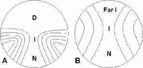
that is also considerably narrower than provided by a FT bifocal.

A common method to represent the optics of PALs is with contour plots of the spherical equivalent and unwanted astigmatism powers as shown in Figures 4 and 5. Because of the complex nature of the optics there are literally an infinite number of possible PAL designs and dozens of different designs are currently available. Although most current PALs defy clear categorization, it is instructive to consider the differences between a “hard” and “soft” design. The lens in Figure 4 shows characteristics of a hard design. Relatively speaking, a lens of hard design has wider error-free distance and near-viewing zones, the area of the lens with unwanted astigmatism is relatively small, and the magnitude of the unwanted astigmatism is large. The separation between the distance and near centers is shorter and the rate of power change along the corridor is greater. The lens in Figure 5 shows soft design characteristics: narrower error-free distance and near-viewing areas, larger area of unwanted astigmatism but of lower magnitude, distance and near centers are farther apart, and a lower rate of power change in the corridor.

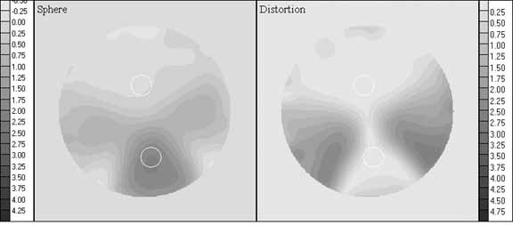
Fig. 4 Contour plots of spherical equivalent power (left) and unwanted astigmatism (right) for SOLA VIP, plano distance power, +2.00 D add. Contours in 0.25 D steps.

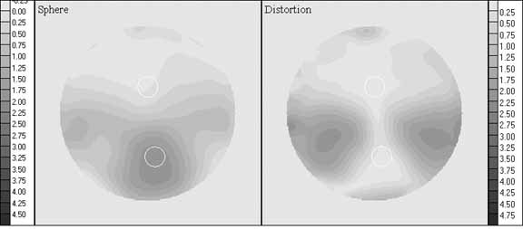
Fig. 5 Contour plots of spherical equivalent power (left) and unwanted astigmatism (right) for Varilux Comfort, plano distance power, +2.00 D add. Contours in 0.25 D steps.

To accommodate the convergence that occurs with viewing at closer distances, the central power corridor is nasally angled toward the bottom of the lens to accommodate ocular convergence at near-viewing distances. Older PAL designs used the same lens for right and left lenses but angled in opposite directions. This approach resulted in the pattern of zone widths and unwanted astigmatism being different to the two eyes. Most current PALs use different lenses for right and left (essentially mirror images of one another) in order to present the same optical characteristics to each eye.

The width and area of the error-free distance, intermediate, and near viewing as well as the magnitude and distribution of unwanted astigmatism can vary significantly across lens designs.9,10 There is considerable interdependence of the sizes and locations of the viewing zones and the magnitude of unwanted astigmatism that make it currently impossible to design a lens that is optimized for all optical attributes. Hence, a particular PAL design may optimize one viewing zone or characteristic, but it is at the expense of the other zones or characteristics.

The widths and areas of the three viewing zones (distance, intermediate, and near) and the magnitude of unwanted astigmatism have been reported.11 The mean measurements are shown graphically in Figure 6. Analysis showed that even the largest intermediate and near error-free zones are smaller than those required to view a typical computer screen or standard paper respectively,11 and also smaller than the normal amount of ocular rotation used to view noncentral targets.12 This means that the PAL wearer must learn to move their head more and their eyes less in viewing noncentral objects and/or tolerate some blurof typical noncentral foveally fixated objects. It is most likely that the head and eye movement patterns are altered by PAL wearers,13 but the high acceptance and preference rates for PALs also indicate that patients fairly readily are able to do so.

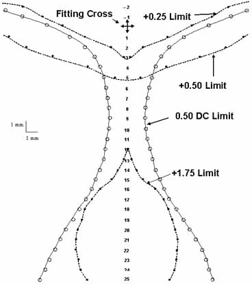
Fig. 6 Mean contours of 28 progressive addition lenses with nominal add of +2.00; data acquired in 1-mm vertical steps. Contour for +1.75 add shown because of greater consistency across lenses. For conversion to visual fixation through the lens, 1 mm is approximately 2 degrees of eye rotation.

PRESCRIBING PROGRESSIVE ADDITION LENSES

For most patients a PAL satisfies general vision needs better than a segmented bifocal. PALs should be considered a first option for general visual use, unless cost is a consideration or the patient has specific occupational or other visual needs that require the wider error-free fields provided by segmented bifocals.

Current successful bifocal or trifocal wearers will remain successful with same lens design, although they would likely prefer the advantages of a PAL. A large percentage of successful bifocal wearers prefer a PAL if given the choice,8 although there is some risk in making the change. Determine if the bifocal-wearing patient has specific occupational or other vision needs that preclude recommending change to a PAL. Otherwise, the patient can be advised of the vision and cosmetic differences between the lens types in order to decide upon a possible change.

For a first-time PAL wearer, selection of the particular PAL design should consider the patient's specific visual needs. If a patient is successfully wearing a particular design of PAL, they will likely continue to be successful with the same design. However, consideration should be given to a different PAL design if it better meets their specific visual needs.

As a direct result of the trade-offs in PAL design and the fact that the various designs utilize different trade-offs, some PALs can be expected to provide better vision at distance, intermediate, near or various combinations of those distances. Ratings of 28 PAL designs based upon the widths and areas of the distance, intermediate and near-viewing zones and also the magnitude of unwanted astigmatism are presented in Tables 3 to 7.11 These tables identify those lenses that can best meet the specific visual needs of particular patients. Just as there is a range of optical characteristics among PALs, there is also a range of visual needs among patients. The clinical task is to match the two.

Table 3 shows lens ratings along the single attributes of distance zone, intermediate zone, and astigmatism. These ratings are useful for those patients for whom there is a single over-riding need for one of those attributes. For example, the distance rankings are used for patients who drive a lot or are involved in outdoor work and have only occasional need for intermediate and near vision. The intermediate rankings are used for patients who want a general purpose PAL but whose primary need is viewing a computer or performing a manufacturing task at intermediate viewing distances. However, such patients may benefit even more from an occupational progressive lens (see section on occupational progressive lenses [OPLs]). The rankings based on astigmatism are used for those patients who are very sensitive to unwanted astigmatism and for whom this is the most important lens attribute.


TABLE 3. Calculated ratings for the distance zone, intermediate zone, and unwanted astigmatism.


Specialty usage—calculated ratings
DistanceRatingIntermediateRatingAstigmatismRating
SOLA Percepta88.1Zei Gradal Top91.3J&J Definity93.3
Younger Image87.4J&J Definity91.1Varlx Panamic70.0
Shamr Genesis83.6Pentx AF Mini87.2AO Pro 1569.3
Ess Spr No-lne83.2Sig Nav Precsn84.6AO Compact66.7
Vis Ease Outlk77.2AO Pro 1584.6Rdnstk Life AT66.0
AO b'Active69.3HoyaLux ECP83.6Pentx AF Mini61.3
Sig Kodak67.1Rdnstk Life AT82.7Pentx AF 15061.3
Zei Gradal Top65.4SOLAMax76.7AO b'Active60.7
Ess Natural54.6AO b'Active74.8Sig Kod Precise60.7
J&J Definity53.0Sig Kodak71.0SOLAMax59.3
SOLA VIP47.9Hoya Sum CD70.0Shamr Genesis55.3
Rdnstk Life XS47.8Ess Adaptar62.0Younger Image54.0
HoyaLux ECP47.4SOLA XL61.7Shamr Piccolo54.0
Pentx AF 15043.5Younger Image61.0Ess Adaptar48.0
Varlx Panamic39.3Ess Natural60.8Hoya Sum CD47.3
Sig Kod Precise37.3Varlx Panamic60.2Rdnstk Life XS46.7
AO Pro 1536.4Pentx AF 15059.1Sig Kodak43.3
Ess Adaptar35.3Shamr Genesis58.9Vis Ease Outlk42.0
Varlx Comfort34.7Hoya GP Wide57.8Varlx Comfort39.3
Hoya Sum CD30.1Varlx Comfort45.4Ess Natural38.7
Sig Nav Precsn29.1Vis Ease Outlk44.0Hoya GP Wide38.0
SOLA XL24.9Shamr Piccolo43.2Zei Gradal Top37.3
Hoya GP Wide24.5Sig Kod Precise42.3HoyaLux ECP35.3
AO Compact23.6SOLA VIP35.9SOLA XL31.3
Shamr Piccolo23.1AO Compact31.9Sig Nav Precsn30.0
Rdnstk Life AT17.6SOLA Percepta30.7SOLA Percepta30.0
Pentx AF Mini16.2Rdnstk Life XS27.6SOLA VIP8.0
SOLAMax7.1Ess Spr No-lne10.8Ess Spr No-lne-29.3

Higher ratings indicate larger and wider areas of vision and lower astigmatism magnitude. These ratings are useful for patients with a single over riding need for distance vision, intermediate vision, or reduction of unwanted astigmatism. (Reprinted with permission of Optometry.)


Table 4 shows ratings based only on the near-viewing zone. These ratings are useful for those patients for whom near vision is the single overriding need. This includes patients who perform extensive near tasks yet also desire a general purpose PAL. It also includes emmetropic patients who intend to use the lenses primarily as reading glasses but also desire a general purpose PAL. An OPL should be considered for these patients. The near ratings in Table 4 are directly derived from width and area magnitudes. As result, the ratings generally increase with greater fitting height because a greater fitting height necessarily results in a larger near-viewing zone for all lenses. The larger ratings for greater fitting heights represent the fact that the patient will have a larger and wider near-viewing zone with a greater fitting height. Only a few lenses provide any near addition for a fitting height of 16 mm. Note also that the lens rankings change somewhat as a function of the fitting height. This is because the manner in which the near zone changes toward the bottom of the lens is different for the various lenses


TABLE 4. Calculated ratings for near zone


Near specialty use—calculated ratings
Fit height 16RatingFit height 18RatingFit height 22RatingFit height 26Rating
Shamr Piccolo28.0Shamr Piccolo45.1Shamr Piccolo76.8SOLA VIP111.3
Rdnstk Life XS27.2AO Compact41.1SOLA VIP76.2SOLAMax106.9
AO Compact24.0Rdnstk Life XS40.2SOLAMax74.0Shamr Piccolo103.8
SOLA VIP22.5SOLA VIP38.8Rdnstk Life XS71.9Rdnstk Life XS102.9
Hoya Sum CD17.1SOLAMax38.3AO Compact65.9Hoya GP Wide98.3
SOLAMax16.3Vis Ease Outlk30.4Ess Spr No-lne63.3Ess Spr No-lne80.1
Sig Kod Precise14.8Ess Spr No-lne29.8Hoya GP Wide59.2Hoya Sum CD80.1
Vis Ease Outlk13.0Sig Kod Precise28.6Sig Kod Precise57.3Varlx Comfort80.1
Hoya GP Wide3.4Varlx Comfort26.6Varlx Comfort56.9HoyaLux ECP78.1
J&J Definity0.0Shamr Genesis25.7Shamr Genesis54.2Sig Nav Precsn77.2
Varlx Panamic0.0Hoya Sum CD23.2Sig Nav Precsn52.0Sig Kod Precise74.4
AO Pro 150.0SOLA XL22.8Vis Ease Outlk52.0AO Compact71.9
Rdnstk Life AT0.0Varlx Panamic21.6SOLA Percepta50.1SOLA Percepta67.0
Pentx AF Mini0.0SOLA Percepta20.8SOLA XL48.7Shamr Genesis63.2
Pentx AF 1500.0Pentx AF Mini20.2Hoya Sum CD46.6Pentx AF 15062.9
AO b'Active0.0Ess Adaptar19.7Sig Kodak46.3Sig Kodak61.4
Shamr Genesis0.0HoyaLux ECP15.5AO b'Active44.8SOLA XL61.3
Younger Image0.0AO b'Active14.6Ess Adaptar43.9Ess Adaptar60.6
Ess Adaptar0.0Sig Kodak14.1Rdnstk Life AT43.6Vis Ease Outlk59.5
Sig Kodak0.0Rdnstk Life AT13.1Varlx Panamic42.6AO b'Active58.3
Varlx Comfort0.0Sig Nav Precsn13.0Pentx AF Mini41.9Varlx Panamic56.4
Ess Natural0.0Younger Image12.5HoyaLux ECP41.1Rdnstk Life AT56.2
Zei Gradal Top0.0AO Pro 159.8Pentx AF 15041.0Zei Gradal Top55.6
HoyaLux ECP0.0Hoya GP Wide9.4Younger Image40.8Pentx AF Mini54.9
SOLA XL0.0Pentx AF 1508.7AO Pro 1540.0AO Pro 1549.5
Sig Nav Precsn0.0J&J Definity5.4Zei Gradal Top35.0Younger Image45.3
SOLA Percepta0.0Ess Natural0.0J&J Definity24.9J&J Definity12.8
Ess Spr No-lne0.0Zei Gradal Top0.0Ess Natural20.0Ess Natural9.8

These ratings are useful for those patients for whom near vision is the single overriding need. Ratings increase with greater fitting heights commensurate with the greater near viewing zone sizes thereby attained. (Reprinted with permission of Optometry.)


The ratings in Table 5 combine viewing zones and are based on equal weightings of the distance and intermediate ratings and the intermediate and near (fitting height of 22 mm) ratings. The two columns on the left do not consider the amount of unwanted astigmatism, whereas those on the right include a 25% weighting of astigmatism. The distance/intermediate ratings apply to patients with primary visual needs at those two distances and for whom near viewing is not as important. This includes drivers or those with outdoor occupations and recreations who have distance and intermediate viewing needs but for whom near viewing is not as important. The intermediate and near category applies to patients who largely work indoors and primarily perform visual tasks at those viewing distances and for whom distance vision is not as important. The ratings that include astigmatism weighting apply to patients with sensitivity to unwanted astigmatism.


TABLE 5. Combination ratings for distance/intermediate, and for intermediate/near (fitting height of 22 used in rating)


Specialty usage combinations
Without astigmatism weightingWith 25% astigmatism weighting
Distance and intermediateRatingIntermediate and near (FH 22)RatingDistance and intermediateRatingIntermediate and Near (FH 22)Rating
Zei Gradal Top78.4SOLAMax75.4J&J Definity77.4SOLAMax71.4
Younger Image74.2Sig Nav Precsn68.3AO b'Active69.2J&J Definity66.8
J&J Definity72.1Pentx AF Mini64.5Younger Image69.1AO Pro 1564.0
AO b'Active72.1Rdnstk Life AT63.1Zei Gradal Top68.1Rdnstk Life AT63.9
Shamr Genesis71.3Zei Gradal Top63.1Shamr Genesis67.3Pentx AF Mini63.7
Sig Kodak69.1HoyaLux ECP62.3AO Pro 1562.7AO b'Active60.0
HoyaLux ECP65.5AO Pro 1562.3Sig Kodak62.6Sig Nav Precsn58.7
Vis Ease Outlk60.6Shamr Piccolo60.0HoyaLux ECP58.0Shamr Piccolo58.5
AO Pro 1560.5AO b'Active59.8Vis Ease Outlk56.0Zei Gradal Top56.7
SOLA Percepta59.4Sig Kodak58.7Varlx Panamic54.8Shamr Genesis56.2
Ess Natural57.7Hoya GP Wide58.5Rdnstk Life AT54.1Varlx Panamic56.0
Sig Nav Precsn56.9Hoya Sum CD58.3Pentx AF Mini54.1HoyaLux ECP55.6
Pentx AF Mini51.7J&J Definity58.0Pentx AF 15053.8Hoya Sum CD55.6
Pentx AF 15051.3Shamr Genesis56.5Ess Natural52.9Sig Kodak54.8
Rdnstk Life AT50.1SOLA VIP56.0SOLA Percepta52.0Hoya GP Wide53.4
Hoya Sum CD50.1SOLA XL55.2Sig Nav Precsn50.2AO Compact53.3
Varlx Panamic49.7Ess Adaptar52.9Hoya Sum CD49.4Pentx AF 15052.9
Ess Adaptar48.6Varlx Panamic51.4Ess Adaptar48.5Sig Kod Precise52.5
Ess Spr No-lne47.0Varlx Comfort51.2SOLAMax46.3Ess Adaptar51.7
SOLA XL43.3Younger Image50.9Sig Kod Precise45.0Younger Image51.7
SOLAMax41.9Pentx AF 15050.1Hoya GP Wide40.4SOLA XL49.2
SOLA VIP41.9Sig Kod Precise49.8SOLA XL40.3Rdnstk Life XS49.0
Hoya GP Wide41.2Rdnstk Life XS49.7Rdnstk Life XS39.9Varlx Comfort48.2
Varlx Comfort40.1AO Compact48.9Varlx Comfort39.9Vis Ease Outlk46.5
Sig Kod Precise39.8Vis Ease Outlk48.0Shamr Piccolo38.4SOLA VIP44.0
Rdnstk Life XS37.7SOLA Percepta40.4AO Compact37.5Ess Natural39.9
Shamr Piccolo33.1Ess Natural40.4SOLA VIP33.4SOLA Percepta37.8
AO Compact27.7Ess Spr No-lne37.0Ess Spr No-lne27.9Ess Spr No-lne20.4

The distance/intermediate ratings apply to patients with primary visual needs at those 2 distances, near viewing is not factored. The intermediate and near category applies to patients that primarily perform visual tasks at those viewing distances and for whom distance vision is not as important. The ratings that include astigmatism weighting apply to patients with sensitivity to unwanted astigmatism. (Reprinted with permission of Optometry.)


The ratings in Table 6 apply for general usage needs. They combine ratings for distance, intermediate, and near-viewing zones or only distance and near zones; ratings are provided based on fitting height of both 18 and 22 mm. The ratings based upon all three zones apply for patients with general viewing needs at all three distances. If the intermediate viewing zone is not particularly important to the patient, then the ratings based on distance and near apply. Unwanted astigmatism is not factored into the ratings in Table 6. The ratings in Table 7 are the same as in Table 6 except that unwanted astigmatism is factored into the rating. These are for patients with general viewing needs and for whom reduced astigmatism is also important.


TABLE 6. General usage combination ratings—no weighting for unwanted astigmatism


General usage combinations—no astigmatism weighting
Distance, intermediate & near (FH 18)RatingDistance, intermediate & near (FH 22)RatingDistance and near (FH 18)RatingDistance and near (FH 22)Rating
Shamr Genesis56.1Shamr Genesis65.6Ess Spr No-lne56.5Ess Spr No-lne73.3
Younger Image53.6Zei Gradal Top63.9Shamr Genesis54.7SOLA Percepta69.1
AO b'Active52.9Younger Image63.1SOLA Percepta54.4Shamr Genesis68.9
Zei Gradal Top52.2AO b'Active63.0Vis Ease Outlk53.8Vis Ease Outlk64.6
Sig Kodak50.8Sig Kodak61.5Younger Image49.9Younger Image64.1
Vis Ease Outlk50.5Vis Ease Outlk57.7Rdnstk Life XS44.0SOLA VIP62.0
J&J Definity49.9HoyaLux ECP57.4SOLA VIP43.3Rdnstk Life XS59.8
HoyaLux ECP48.8J&J Definity56.4AO b'Active42.0AO b'Active57.0
SOLA Percepta46.5SOLA Percepta56.3Sig Kodak40.6Sig Kodak56.7
AO Pro 1543.6Sig Nav Precsn55.3Shamr Piccolo34.1Zei Gradal Top50.2
Sig Nav Precsn42.3AO Pro 1553.6Sig Kod Precise33.0Shamr Piccolo49.9
Ess Spr No-lne41.3SOLA VIP53.3Zei Gradal Top32.7Sig Kod Precise47.3
Pentx AF Mini41.2SOLAMax52.6AO Compact32.4Varlx Comfort45.8
Hoya Sum CD41.1Ess Spr No-lne52.4HoyaLux ECP31.5AO Compact44.8
SOLA VIP40.9Rdnstk Life XS49.1Varlx Comfort30.7HoyaLux ECP44.3
SOLAMax40.7Hoya Sum CD48.9Varlx Panamic30.4Pentx AF 15042.2
Varlx Panamic40.3Pentx AF Mini48.4J&J Definity29.2Hoya GP Wide41.8
Ess Adaptar39.0Rdnstk Life AT48.0Ess Adaptar27.5Varlx Panamic40.9
Rdnstk Life XS38.5Pentx AF 15047.9Ess Natural27.3SOLAMax40.6
Ess Natural38.5Shamr Piccolo47.7Hoya Sum CD26.6Sig Nav Precsn40.6
Rdnstk Life AT37.8Varlx Panamic47.3Pentx AF 15026.1Ess Adaptar39.6
Shamr Piccolo37.1Hoya GP Wide47.2SOLA XL23.8J&J Definity39.0
Pentx AF 15037.1Ess Adaptar47.1AO Pro 1523.1Hoya Sum CD38.4
SOLA XL36.4Varlx Comfort45.7SOLAMax22.7AO Pro 1538.2
Sig Kod Precise36.1Sig Kod Precise45.6Sig Nav Precsn21.1Ess Natural37.3
Varlx Comfort35.6Ess Natural45.1Pentx AF Mini18.2SOLA XL36.8
AO Compact32.2SOLA XL45.1Hoya GP Wide17.0Rdnstk Life AT30.6
Hoya GP Wide30.6AO Compact40.5Rdnstk Life AT15.3Pentx AF Mini29.0

Distance/intermediate/near ratings useful for patients with general visual needs, distance/near ratings useful for patients without intermediate needs. Ratings calculated for fitting height (FH) of 18 and 22, representative of low and high fitting heights, respectively. (Reprinted with permission of Optometry.)


TABLE 7. General usage combination ratings


General usage combinations—25% astigmatism weighting
Distance, intermediate & near (FH 18)RatingDistance, Intermediate & near (FH 22)RatingDistance and near (FH 18)RatingDistance and near (FH 22)Rating
J&J Definity60.7J&J Definity65.6Shamr Genesis54.8Shamr Genesis65.5
Shamr Genesis55.9Shamr Genesis63.0Younger Image50.9Younger Image61.6
AO b'Active54.8AO b'Active62.4Vis Ease Outlk50.8SOLA Percepta59.3
Younger Image53.7Younger Image60.8SOLA Percepta48.3Vis Ease Outlk58.9
AO Pro 1550.0AO Pro 1557.6AO b'Active46.6AO b'Active57.9
Sig Kodak48.9Zei Gradal Top57.3J&J Definity45.3Rdnstk Life XS56.5
Zei Gradal Top48.5Sig Kodak56.9Rdnstk Life XS44.7Sig Kodak53.4
Vis Ease Outlk48.4SOLAMax54.3Sig Kodak41.3J&J Definity52.5
Varlx Panamic47.8Vis Ease Outlk53.8AO Compact40.9Shamr Piccolo50.9
Pentx AF Mini46.2Varlx Panamic53.0Varlx Panamic40.3Sig Kod Precise50.6
HoyaLux ECP45.5Rdnstk Life AT52.5Sig Kod Precise39.9AO Compact50.2
SOLAMax45.4HoyaLux ECP51.9Shamr Piccolo39.1SOLA VIP48.5
Rdnstk Life AT44.8Pentx AF Mini51.6Ess Spr No-lne35.1Varlx Panamic48.2
Pentx AF 15043.2Pentx AF 15051.2Pentx AF 15034.9Ess Spr No-lne47.6
Hoya Sum CD42.7SOLA Percepta49.7AO Pro 1534.6Pentx AF 15047.0
SOLA Percepta42.4Sig Kod Precise49.4SOLA VIP34.5Zei Gradal Top47.0
Sig Kod Precise42.2Shamr Piccolo49.3Zei Gradal Top33.9AO Pro 1546.0
Shamr Piccolo41.3Sig Nav Precsn48.9Varlx Comfort32.8SOLAMax45.3
Ess Adaptar41.2Hoya Sum CD48.5Ess Adaptar32.6Varlx Comfort44.2
AO Compact40.8Rdnstk Life XS48.5HoyaLux ECP32.4HoyaLux ECP42.0
Rdnstk Life XS40.6Ess Adaptar47.3SOLAMax31.9Ess Adaptar41.7
Sig Nav Precsn39.2AO Compact47.0Hoya Sum CD31.8Hoya GP Wide40.9
Ess Natural38.5Hoya GP Wide44.9Ess Natural30.2Hoya Sum CD40.6
Varlx Comfort36.5Varlx Comfort44.1Pentx AF Mini29.0Rdnstk Life AT39.5
SOLA XL35.2Ess Natural43.5Rdnstk Life AT28.0Sig Nav Precsn37.9
SOLA VIP32.6SOLA VIP42.0SOLA XL25.7Ess Natural37.6
Hoya GP Wide32.4SOLA XL41.6Sig Nav Precsn23.3Pentx AF Mini37.1
Ess Spr No-lne23.6Ess Spr No-lne32.0Hoya GP Wide22.2SOLA XL35.4

Same as Table 4 but with 25% weighting for unwanted astigmatism. Same use as Table 4 but for patients with sensitivity to unwanted astigmatism. (Reprinted with permission of Optometry.)


FITTING PROGRESSIVE ADDITION LENSES

Both the vertical and horizontal positioning of the PAL within the eye of the frame are critical. Because the near addition in a PAL is relatively low in the lens, a frame with a relatively large B (vertical) dimension should be selected, preferably larger than 30 mm. Frames with adjustable nose pads are also advisable, to enable postdispensing adjustment of the location of the lenses before the eyes. The frame must be properly adjusted to include pantoscopic angle, vertex distance, and vertical wearing position prior to measuring the lens location.

PALs are designed to have the fitting cross placed directly in front of the pupil with normal straight-ahead gaze. For each design this provides the optimal location of the viewing zones and the optimal binocular use of the lenses. The vertical height of the fitting cross should be measured from the pupil down to the lowest edge of the lens in the frame. The ratings in Table 4 show that considerably greater near areas and widths are attained with greater fitting heights. Only a few PALs provide a near-viewing zone with a fitting height of 16, and a fitting height of 22 provides considerably greater near zone than a fitting height of 18 for all of the lenses. Small frames, which result in shorter fitting heights, require careful selection of PAL design (far left columns of Table 2).

Even with a properly selected short-corridor PAL, fitting heights shorter than 18 necessarily result in some compromise of the near-viewing zone and the patient should be advised of such. The compromised near zone will be noticeable in conditions of low illumination (menu in a restaurant) because of a larger pupil, high reading demands (office work or reading a book in the evening), or viewing small print (phone book). Many patients consider these as reasonable trade-offs for the fashionable small frame. Separate reading glasses or OPLs can be prescribed for specific near-viewing tasks.

Accurate measurement of the PD is particularly critical for successful wearing of a PAL. This is because of the narrowness of the intermediate channel that is directly below the fitting cross. The narrowest portion of the average PAL (Fig. 6) is approximately 3 mm, or about the same size as the pupil of the eye. If the pupils of both eyes are to be able to simultaneously view through the channel, there is essentially no tolerance for error in the separation of the two lenses. Any error in the separation of the lenses relative to the PD of the patient results in one of the eyes viewing through an edge of the channel when the other is centered in it. Improper measurement of PD may be the largest reason for patient nonacceptance of PALs.

PD measurement with a pupillometer is probably the most accurate method. Accurate measurement of the total PD is the most important, however, it is also advisable to specify the split, or monocular components of the PD as enabled by a pupillometer.

ADAPTATION TO PALS

Some patients have difficulty adapting to PALs. However, this problem has lessened considerably with newer designs and the high acceptance rates of PALs indicate this problem is becoming uncommon. Adaptation problems can be related to spatial distortion resultant from the pattern of unwanted astigmatism in the lower quadrants of the lens. Such patients will report swimming sensations, spatial disorientation, warped appearance of lines, or vague complaints. Other patients may have difficulty with the width of the distance, intermediate, or near-viewing zones. Distortion is less and zones are wider for lower adds, therefore, adaptation is easiest for the beginning presbyope. Adaptation to a PAL will be more difficult for a first-time wearer with a higher add. As with most spectacle lens adaptation, it may take up to 2 weeks of continuous wear for adaptation.

Adaptation difficulties can often be managed by adjusting the pantoscopic angle, the vertex distance, or the fitting height (if the frame has adjustable nose pads). Verify that the distance between lens centers matches the patient's PD; mismatch can certainly cause adaptation problems. If the patient difficulties concern the width or area of one of the viewing zones, consult Tables 3 through 7 to determine if the complaints match the lens characteristics and whether another PAL design would resolve the problem. If the problems cannot be resolved, common industry practice is to replace the PAL lenses with bifocals with no additional charge to doctor or patient.

Back to Top
OCCUPATIONAL PROGRESSIVE LENSES

DESIGN AND OPTICAL PROPERTIES

OPLs utilize progressive power optics and are designed primarily to meet typical indoor viewing needs of presbyopic patients. OPLs provide near vision in the lower portion of the lens, a wide field of intermediate vision in the straight-ahead position, and far intermediate vision in the top of the lens. OPLs are not designed to meet typical distance viewing needs and they are not intended to meet general vision needs. The need for this type of lens has been driven by the large numbers of people working in offices and at computers. However, OPLs also meet the viewing needs of many people who work in other indoor environments.

As with PALs there is wide variation in OPL designs. Stylized designs of both a PAL and an OPL are shown in Figure 7 to demonstrate the principal differences between the two. Most OPL designs do not include any distance correction whereas a wide clear field of distance vision is important to PAL design. OPLs are designed to provide a wide field of intermediate vision, contrasted with the narrow intermediate vision provided by PALs. The unwanted peripheral astigmatism that necessarily accompanies any lens with progressive optics is typically located higher in the lens in an OPL compared to a PAL because indoor office work comprises more downward viewing than typical outdoor environments. The magnitude of the unwanted astigmatism will typically be less with an OPL than with a PAL. This is because the power change in an OPL is less (the OPL typically does not include the full distance power) and the poles of the power extremes are farther apart than for a PAL. Both of these factors serve to reduce the amount of unwanted astigmatism.

Fig. 7 Stylized contour plots of astigmatism with viewing zone locations for: (A) progressive addition lens and (B) occupational progressive lens.

OPLs are commonly prescribed by writing the typical distance prescription with near addition and specifying an OPL design. The laboratory fabricates the lens to have the prescribed near power in the bottom of the lens. This is atypical because all other lenses are fabricated to have the prescribed distance power at a designed location near the center or upper portion of the lens. The powers provided in the middle and upper portions of the OPL are determined by the lens design relative to the near prescription.

Because the near power is used as the fabrication reference for OPLs, the power change that occurs in an OPL is specified from the near reference. This results in specification of a negative power progression that occurs with increasing height in an OPL, exactly the opposite manner of specifying power change in a PAL. This power change in an OPL is referred to as a power “degression.”

The amount of degression in an OPL, along with the add power, determines the power and hence the amount of distance blur in the top portion of the lens. Most of the OPL designs have a power degression less than the near add, which results in an add of 0.25 to 0.75 D in the top of the lens. This amount of plus in the top of the lens is usually acceptable for an indoor environment. Although a full distance power in the top of the lens may be needed for some patients, it may not be the best correction to meet the needs of many other patients and, in some ways, degression to the full distance power defeats some of the advantages of the OPL design. The lower degression (compared to the full degression to accomplish full distance power) enables a wider corridor of clear intermediate vision and lower magnitude of unwanted astigmatism. Selection of the amount of degression involves a trade-off between clarity of distance vision and the usable field of intermediate and near vision.

PRESCRIBING OCCUPATIONAL PROGRESSIVE LENSES

An important factor in the success of most OPLs is the far-intermediate power in the top of the lens. With far-intermediate correction in the top of the lens the patient can navigate hallways, recognize co-workers, attend meetings, etc. This is important because the patient does not need to remove the glasses each time they leave their desk as they would need to do with reading glasses. Most patients will not use computer glasses that need to be removed each time the leave their desk. The intermediate and near-viewing areas of an OPL enable the patient to function at their desk and computer, whereas the far intermediate zone in the top of the lens enables the patient to navigate the office while wearing the lenses.

Work at a computer is the most common task for which OPLs are designed and prescribed. Bifocals and PALs do not work well for computer users who require a lens addition for viewing intermediate distances. Early presbyopic patients with near adds of approximately 1.50 D or less have enough remaining accommodation to focus on the computer display through the distance portion of the lens. However, once the patient requires an add for intermediate viewing, they can no longer comfortably use a bifocal or PAL. A bifocal lens is usually prescribed for a 40-cm viewing distance and the bifocal segment is located for a downward viewing angle of approximately 25 degrees. The computer is typically at a distance of 50 to 70 cm and a downward viewing angle of 10 to 20 degrees. The bifocal wearer must awkwardly tilt the head back and lean toward the computer display to see the screen clearly through the near portion of the lens. A progressive addition lens is likewise limiting at the computer because the area of the lens containing the intermediate power is small and narrow, thereby requiring head instead of eye movements to scan the computer screen. An OPL has a wide corridor of usable intermediate power that is located well for computer viewing.

OPLs meet visual needs in many other situations in addition to computer use. They work well for many indoor needs such as housework, manufacturing facilities, medical offices, indoor sales, etc. They also work well instead of bifocals for pediatric patients. For pediatric patients, the OPL should be designed to provide some distance vision in the top of the lens for viewing the front of a classroom. OPLs are also a good substitute for single vision reading glasses, because they provide a good reading area but also far-intermediate vision in the top of the lens for viewing objects such as a television across the room.

Several OPLs are available in a series of discrete degression amounts. These include Access (SOLA International, San Diego, CA), Cosmolit Office (Rodenstock, Munchen, Germany), Office (Shamir Insight, Inc., aka Desktop by Hoya, San Diego, CA). The degression amounts available for each are shown in Table 8. The specific degression power is typically selected by the optical laboratory based on the near add power in the prescription as indicated in Table 8. The amount of add remaining in the top of the lens is shown in the right column of Table 8. The clinician can specify that the laboratory provide a nonstandard degression if patient viewing distances and intended usage vary significantly from typical indoor usage. For example, it is often possible to select a degression amount that matches the patient's near add, thereby providing the distance power in the top of the lens. This may be desirable for a child in a classroom or for a stockbroker to see the ticker display across the room. Although this approach provides a small area of distance correction in the top of the lens, it is too small in area to meet nonindoor distance viewing requirements.


TABLE 8. Occupational progressive lenses that are available in a limited series of degression values


 DegressionAdd rangeAdd power in top
Access0.751.00 to 1.500.25 to 0.75
 1.251.75 to 2.500.50 to 1.25
Cosmolit Office1.001.00 to 1.750.00 to 0.75
 1.752.00 to 2.500.25 to 0.75
Office0.751.00 to 1.500.25 to 0.75
 1.251.75 to 2.000.50 to 0.75
 1.752.25 to 2.500.50 to 0.75

Each degression value serves a small range of near addition powers, the resulting range of add power in the top of the lens for the add range is shown in the right column.


Gradal (Carl Zeiss Optical, Inc., Chester, VA) is an OPL that has a full range of degression powers in 0.25 D steps; the degression amount is selected by the laboratory so that +0.50 D add remains in the top of the lens, unlike the lenses in Table 8 in which the amount of add in the top of the lens varies dependent on near add.

Two OPLs, Tact (Hoya) and Technica (American Optical, New York, NY) are designed to have a small area of distance power in the top of the lens (i.e., the degression amount equals the add amount). The distance viewing area is small and located high in the lens. These lenses can be used for patients with limited but critical distance viewing needs while in an indoor environment.

Back to Top
ANISOMETROPIA—VERTICAL IMBALANCE AT NEAR
Any spectacle-wearing patient with anisometropia will obtain different amounts of prism to each eye when viewing away from the optical center. For example, what differential prism is generated when the following patient depresses their gaze 20 degrees to read?

OD: -2.00 DS

OS: -5.00 DS

When the patient depresses their eyes 20 degrees, this represents viewing through a lens location that is 10 mm from the optical center (2 degrees = approximately 1 mm). By Prentice's rule, the amount of prism (in prism diopters or Δ) is equal to the distance from the optical center (in centimeters) multiplied by the power. Hence, the prism at that lens location in the right eye is 2Δ base-down (1 cm × 2 D) and in the left eye it is 5Δ base-down. This is a net of 3Δ base-down in the left eye.

This amount of induced differential prism might be expected to cause significant difficulty for the patient, but this is not always the case. It has been shown that most anisometropic patients will measure orthophoria in both straight-ahead and in down-gaze through spectacles.14 This seems to indicate that binocular eye movements can adjust to the differential prism demands. If the patient is wearing single vision lenses, the patient can also adjust to this problem by using more head movement than eye movements when viewing peripheral objects thus maintaining fixation close to the optical centers of the lenses and avoiding the differential prism effects. However, when a patient is prescribed multifocals, they are now required to view through a peripheral portion of the lenses in order to use the near portion of the lens. The bifocal-wearing patient cannot avoid the induced prism problem by using head instead of eye movements. Some bifocal wearing patients have difficulty with this and resultant discomfort while reading.

It can be determined if this is a problem for a particular patient by having them view downward through their spectacle lenses at a typical reading angle, interpose corrective vertical prism before their eyes (in the example above, this would be 3Δ base-up in the left eye), and note if the patient is more comfortable. Vertical phoria or fixation disparity can also be tested in down gaze through the glasses. Observe if the patient is a head mover with their glasses, this is an indication that differential vertical prism may be a problem.

One method of solving this problem is to prescribe a separate pair of reading glasses with the optical centers placed lower in the frame allowing the patient to read without encountering much differential prism.

The most common method of solving this problem is with bicentric grind, or what is referred to as “slab-off.” This is a special grinding technique applied to the back surface of one of the two lenses by the optical laboratory. Essentially the laboratory grinds the back surface with two different grinding centers, one higher than the other. This results in a horizontal line of demarcation that extends across the entire lens. There is a sudden prism jump at that line, and the amount of the prism jump is calculated to eliminate the induced differential prism at a given reading level. The amount of prism in the slab-off can be specified in the laboratory order, or the practitioner can specify the reading level at which prism equalization is desired and the laboratory will calculate the amount. The line is normally placed to be colocated with the top of the bifocal or trifocal segment. This procedure can also be performed on a PAL.

Back to Top
FUTURE OF MULTIFOCAL LENSES
Multifocal lenses are, by far, the most common clinical treatment of presbyopia. Although newer surgical corrections of presbyopia will certainly gain usage in the future, it is likely that multifocal lenses will be a mainstay for quite some time. Progressive addition lenses will continue to gain market share and segmented multifocal lenses will become less common. Newer designs of progressive addition lenses will result in better visual function and special purpose PALs will also become more common.
Back to Top
REFERENCES

1. Bruneni J: Looking Back: An Illustrated History of the American Ophthalmic Industry. Torrance, CA: Optical Laboratories Association, 1994

2. Maitenaz B: Four steps that lead to Varilux. Am J Optom Arch Am Acad Optom 43:441, 1966

3. Sheedy JE, Buri M, Bailey IL, et al: Optics of progressive addition lenses. Am J Optom Physiol Opt 64:90, 1987

4. Cho MH, Barnette CB, Aiken B, et al: A clinical study of patient acceptance and satisfactioo of Varilux Plus and Varilux Inginity lenses. J Am Optom Assoc 62:449, 1991

5. Sullivan CM, Fowler CW: Analysis of a progressive addition lens population. Ophthalmic Physiol Opt 9:163, 1989

6. Gresset J: Subjective evaluation of a new multi-design progressive lens. J Am Optom Assoc 62:691, 1991

7. Borish IM, Hitzeman SA: Comparison of the acceptance of progressive addition multifocals with bldnded bifocals. J Am Optom Assoc 44:415, 1983

8. Boroyan HJ, Cho MH, Fuller BC, et al: Lined multifocal wearers prefer progressive addition lenses. J Am Optom Assoc 66:296, 1995

9. Simonet P, Papineau Y, Lapointe R: Peripheral power variations in progressive addition lenses. Am J Optom Physiol Opt 63:873, 1986

10. Sullivan CM, Fowler CW: Grating visual acuity testing as a means of psychophysical assessment of progressive addition lenses. Optom Vis Sci 66:565, 1989

11. Sheedy J: Progressive addition lenses: matching the specific lens to patient needs. Optometry 75:83, 2004

12. Uemura T, Arai Y, Shimazaki C: Eye-head coordination during lateral gaze in normal subjects. Acta Otolaryngol 90:191, 1980

13. Pedrono C, Obrecht G, Stark L: Eye-head coordination with laterally “modulated” gaze field. Am J Optom Physiol Opt 64:853, 1987

14. Ellerbrock VFG: Effects induced by anisometropic corrections. Am J Optom Arch Am J Optom 19:444, 1942

Back to Top