Chapter 38
The Cross Cylinder
STUART E. WUNSH
Main Menu   Table Of Contents

Search

DETERMINATION OF CYLINDER AXIS
THEORY OF AXIS DETERMINATION
DETERMINATION OF CYLINDER POWER
PRESBYOPIA
ACCOMMODATION
CROSS CYLINDERS AND OTHER REFRACTIVE TECHNIQUES
ASTIGMATISM
REFERENCES

The invention of the cross cylinder can be traced back to the early 19th century. In 1837, the astronomer Sir George Biddle Airy1 made a cylindric lens and used it to correct astigmatism. Astigmatism was not readily recognized in those days, and when instances were found they were reported in the literature. The trial lens sets of that era contained no cylindric lenses; when such lenses were prescribed, they could be obtained only on special order from a few laboratories.

In response to the growing recognition of astigmatism and the need to correct it, a device called the Stokes lens was introduced in 1849.1 This lens consisted of two cylinders, one planoconvex and one planoconcave, with flat surfaces approximated and arranged so that they could be rotated in opposite directions. When the axes of the two cylinders were parallel, the resultant power was zero; when the axes were perpendicular, a spherocylinder with maximal power for that pair of lenses was formed. In practical use, you should first determine the axis of the astigmatism by rotating the lens before the eye, with some arbitrary setting; then, while maintaining the proper axis before the eye, try various strengths of cylinders. Each of the two cylinders in the Stokes lens had a power of approximately 4 diopters (D). The instrument could, therefore, create spherocylinders between 0 and + 4.00 D sph-8.00 D cyl.

In 1885, W.S. Dennett improved the lens mounting and tried to popularize the instrument.2 Edward Jackson realized the instrument's potential for determining cylinder power and reported his results in 1887.3 The Stokes lens remained little more than a curiosity, however, until 1907, when the cross cylinder's usefulness in determining the axis of astigmatism was realized. The modified Stokes lens with axes fixed perpendicular to one another came to be known as the “Jackson crossed cylinder,” but the term cross cylinder is now perhaps more popular.

Although Jackson did describe his findings, it remained for W.H. Crisp, a more prolific writer, to bring this device to worldwide attention.4 The form of the instrument is a fixed arrangement of a plus and a minus cylinder, axes perpendicular, with a handle placed between the two axes. The following powers may be obtained:

  + 0.12 D cyl × 90°-0.12 D cyl × 180°
  + 0.25 D cyl × 90°-0.25 D cyl × 180°
  + 0.50 D cyl × 90°-0.50 D cyl × 180°
  + 1.00 D cyl × 90°-1.00 D cyl × 180°

Written in this form, it is clear that we are dealing with cylinders (cyl). The spherical notation (sph) may be used (i.e., + 0.12 D sph -0.25 D cyl × 180°), but this suggests the presence of spherical power. Some cross cylinder lenses are ground as a sphere on one surface and a cylinder on the other for economic reasons. The optics can be thought of much more easily if the cylindric components are emphasized.

The question of the possible spherical component of the cross cylinder and its effect on the final correction has not been settled. This question has nothing to do with the notation of the lens or whether it is ground as two cylinders or as one sphere and one cylinder, but it is concerned with the total effect of the lens on the object viewed. When it is introduced before the tentative correction, does the cross cylinder change the spherical power, or does it merely expand the conoid of Sturm? Jackson3 and others2,5 believed that the cross cylinder acts as two separate cylinders; it enlarges the conoid of Sturm, but does not change the spherical power. Opposing arguments contend that spherical power has been added to the correction by the cross cylinder and that this must be compensated for when the cross cylinder is removed.

I believe that the cross cylinder, even though it can be expressed in spherical form, is not a -0.50 sphere with a plus cylinder axis 90° away, but rather an infinite series of powers at an infinite number of meridians, resulting in an enlargement of the conoid of Sturm.

Some day, someone will design a three-dimensional model that can be viewed on a screen; this might better clarify the issue.

In point of fact, the question of spherical power in the cross cylinder is moot. Refraction is a dynamic process.6,7 As the final correction for a given patient is approached, all of the parameters of the refraction may be rechecked several times. In this way, any alterations in spheric power that may be induced by the cross cylinder are obviated.

Back to Top
DETERMINATION OF CYLINDER AXIS
The following definition of terms will aid in understanding the mechanical technique of determining cylinder axis with the cross cylinder. The term twirl means a “flipping” of the lens before the eye in such a way that the side of the cross cylinder facing the patient at the beginning of the maneuver comes to face the examiner at the conclusion of the maneuver. The term rotate refers to a clockwise or counterclockwise motion of the cross cylinder in front of the patient, in the plane of the spectacle lens, about an axis parallel to the line of sight. The term correcting cylinder refers to the cylindric lens in the trial frame. This may represent either the tentative or the final correction, depending on the stage of the refraction. The term resultant denotes the total dioptric power obtained when different lenses are superimposed.

The first step in determining cylinder axis is to choose a tentative sphere and cylinder. The sphere is then adjusted so that the patient can read 20/40 (6/12)* or better. At this point, there should be a state of meridional balance, which is achieved when the conoid of Sturm is straddling the retina. (The duochrome test is a method of checking for meridional balance.)


Metric equivalent given in parentheses after Snellen notation.

The cross cylinder is now placed in front of the correcting cylinder, with its handle parallel to the axis of the correcting cylinder. In this position, the axes of the cross cylinder straddle the axis of the correcting cylinder at 45° each. It is explained to the patient that both images to be presented may be slightly blurred, but one may be clearer than the other. The patient is to state which position of the cross cylinder presents the clearer image (position 1 or position 2) or whether they appear alike. The clearer image is the one that is sharper, darker, or more legible. The end point of the test is reached when no difference can be discerned between the two positions of the cross cylinder.

The cross cylinder is then twirled in front of the correcting cylinder. This maneuver reverses the positions of the plus and minus axes of the cross cylinder. If both positions appear equally clear (or equally blurred), then the axis of the correcting cylinder is at the proper meridian and the test for axis is complete. If one position is clearer, the correcting cylinder is rotated toward the axis on the cross cylinder having the same sign as that of the correcting cylinder. Assume that a minus cylinder is being used as our correcting cylinder, and the patient selects the clearer position of the cross cylinder. We locate the minus axis of the cross cylinder in that position and rotate the correcting cylinder toward that axis 5° or 10°. (If plus cylinders were used for correction, we would rotate the correcting cylinder toward the plus axis of the cross cylinder in the preferred position.) The reason for this maneuver is explained later in the chapter. The cross cylinder is then relocated so that its axes once more straddle the axis of the correcting cylinder in its new position, and the test is repeated. When twirling the cross cylinder produces equal clarity (or blurring), the end point of the procedure has been reached and the axis of astigmatism has been identified.

Back to Top
THEORY OF AXIS DETERMINATION
The cross cylinder is particularly sensitive in assisting the patient in the selection of the proper axis of his or her astigmatism. When the cross cylinder straddles the presumed cylinder axis in the trial frame in one position, it creates a new cylinder whose axis is approximately 40° away from the original axis and increases the power of the cylinder; however, in the other position, the axis will jump 40° in the opposite direction but reduce the power. The patient easily perceives this change, seeing the lower powered cylinder as clearer, and the appropriate steps may be taken by the examiner. Many texts at this point refer to the complexity of understanding the mathematics that show why the foregoing occurs and pass onto another topic.

With regard to the cross cylinder and axis determination, comprehending the first paragraph is all you will need to be a successful refractionist. The 
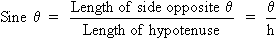
full power of the cylindric lens lies 90° from its axis. For example, a + 1.00 D cyl × 180° has for its power at the 180° meridian 0 D and at the 90° meridian + 1.00 D. What may not be generally appreciated is that between these two meridians (180° and 90°) the lens has dioptric power. In the example just mentioned, this begins with 0 D at 180° and increases at each meridian to the maximum power, + 1.00 D at 90° (Fig. 1). Of course, this applies to any cylinder regardless of power, sign (plus or minus), or axis. A cylinder will have a power of 0 D at its axis and increasing plus or minus power at each meridian, reaching a maximum (i.e., the stated power of the cylinder) 90° from the axis.

Fig. 1. + 1.00 D cyl × 180°. Power indicated at each 10° meridian. (Int Ophthalmol Clin 11:131, 1971)

The power at each meridian of the lens is a function of the sine of the angle between the given meridian and the axis of the cylindric lens. To review, the sine of an angle in a right triangle is determined by the ratio between the length of the side opposite the angle and the length of the hypotenuse of the triangle. For a given angle, , it may be written as follows (Fig. 2).

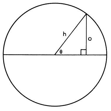
Fig. 2. Sine equals side opposite given angle divided by the length of the hypotenuse. (Int Ophthalmol Clin 11:131, 1971)

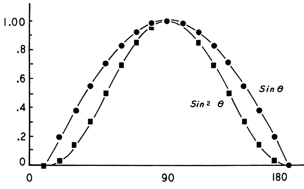
The sine of 0° is 0, the sine of 90° is 1, and the sine of 180° is once again 0. Between 0° and 90°, the values of sine increase from 0 to 1; they show a corresponding decrease between 90° and 180°. The sines of angles from 0° to 180° may be plotted on a graph, as shown in Figure 3 (the round points), and give rise to the sine curve. Many wavelike or cyclic phenomena may be described by a sine curve. In our current example, the changing powers of a cylindric lens seem to follow this curve.

Fig. 3. Curves generated by functions sin and sin2 . Curve sin2 closely approximates changing power of a cylindric lens at each meridian. (Int Ophthalmol Clin 11:131, 1971)

Two additional factors slightly complicate this discussion. First, the relationship between the angle and the cylinder power is more accurately described by the square of the sine. That is, Dm (the dioptric power at any meridian of a cylindric lens) is equal to D (the maximum power of the cylinder) multiplied by the sine squared of the given angle.8 This is written Dm = D sin2 . (The curve of sin2 is described by the square points in Figure 3.) Second, this formula is still only an approximation. The true values for cylinder power are obtained through a more complex formula; however, the values derived by the use of this approximate formula are accurate enough for our purposes.

If two cylinders of equal strength but opposite sign are placed one before the other with axes superimposed, they will neutralize each other. For example, if a -1.00 D cyl × 180° is placed before a + 1.00 D cyl × 180°, the resultant power is zero. The -1.00 D, which is the power in the vertical meridian of one lens, is neutralized by the + 1.00 D in the same position in the other lens. In addition, at each meridian between 0° and 180°, the powers present are equal but of opposite sign, thus neutralizing each other as well.

If, however, the axes were not perfectly aligned, we would have to add, algebraically, the powers present at each meridian and arrive at a resultant power. For example, beginning with a cylinder + 1.00 D × 180°, as pictured in Figure 1, we will superimpose a -1.00 D cyl but place its axis at 170° (10° “off axis”) (Fig. 4). Note that at 90° in Figure 1, we have + 1.00 D; at 90° in Figure 4, we have -0.970 D. The resultant in this meridian is + 0.030 D; this calculation is repeated at each 10° meridian.

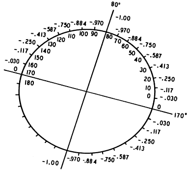
Fig. 4. -1.00 D cyl × 170°. Power indicated at each 10° meridian. (Int Ophthalmol Clin 11:131, 1971)

The resultant is pictured in Figure 5. We have created a spherocylinder, the formula of which may be written + 0.174 D sph-0.348 D cyl × 130°. Note the following: our -1.00 D cylinder no longer neutralizes our + 1.00 D cylinder. A new cylinder has been formed, in which the axis (using minus cylinder notation) is approximately 40° removed from the axes with which we began (i.e., 180° and 170°). A small error in the placement of the axis of the correcting cylinder produces a large displacement of the axis of the resultant cylinder.
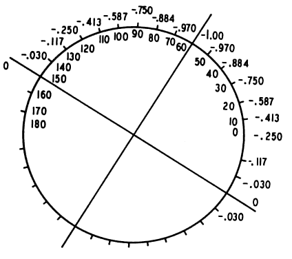
Fig. 5. + 0.174 D sph-0.348 D cyl × 130°. Resultant of superimposing Figures 1 and 4. (Int Ophthalmol Clin 11:131, 1971)

Suppose the correcting cylinder were displaced by an even greater amount. Again, begin with a + 1.00 D cyl × 180° and superimpose a -1.00 D cyl, but this time displace the axis 30° (i.e., axis at 150°; Fig. 6). The resultant of this combination may be seen in Figure 7. The spherocylinder is + 0.50 D sph-1.00 D cyl × 120°. With the correcting cylinder equal in power to the cylinder to be neutralized, an error in axis placement of 30° produces a new astigmatism equal in power to the original cylinder.

Fig. 6. -1.00 D cyl × 150°. Power is indicated at each 10° meridian. (Int Ophthalmol Clin 11:131, 1971)

Fig. 7. + 0.50 D sph-1.00 D cyl × 120°. Resultant of super-imposing Figures 1 and 6 and adding the power at each meridian. (Int Ophthalmol Clin 11:131, 1971)

The power of the resultant spherocylinder has increased from the previous example (see Fig. 5), but the shift in the resultant cylinder axis is not much greater than that produced by shifting the correcting cylinder 10° “off axis.” By moving the correcting cylinder 20° farther off axis (from 170° to 150°), we have moved the resultant cylinder only 10° (from 130° to 120°). It can be shown that further deviation of the correcting cylinder axis produces proportionately smaller shifts in the resultant cylinder axis. The conclusion to be drawn is that a small error in the placement of the correcting cylinder produces almost maximal shifts of the resultant cylinder axis. (This large shift in axis can be perceived by the patient and may be used in determining the correct cylinder axis in refraction. This will be considered in more detail later in the chapter.)

Apply this knowledge to an actual refraction, using an eye that requires a -1.00 D cyl × 180° for correction of ametropia. We have shown previously that a -1.00 D cyl × 180° neutralizes a + 1.00 D cyl × 180° in all meridians. Therefore, we may assume the eye thus corrected contains a + 1.00 D cyl × 180°. That is, it is 1.00 D myopic in the 90° meridian, with progressive decrease in myopia to plano in the 180° meridian, and is corrected by the -1.00 D cylinder. The refracting power of the eye is “too strong” in the 90° meridian, and the image is in the vitreous. This + 1.00 D cyl × 180° we can call the eye cylinder. It must have the same characteristics ascribed to cylindric lenses in the previous section. If the correcting cylinder (-1.00 D cyl × 180°) is precisely superimposed over the eye cylinder (+ 1.00 D × 180°) the resultant is 0 D. If, however, the axis of the correcting cylinder is displaced 10°, as in our previous example, the resultant is a new cylinder, the axis of which is removed approximately 40° from the true axis of astigmatism (see Fig. 5). If the error in the axis of the correcting cylinder is increased, the further shift in the axis of the resultant astigmatism will be small by comparison, as in our previous example in Figure 7. The new astigmatism produced by the improper placement of the correcting cylinder axis we shall call secondary astigmatism. The data given in the previous section for two cylindric lenses applies to the condition of a cylinder correcting an eye with astigmatism.

We have now set the stage for understanding the use of the cross cylinder. In considering the example given of a patient's eye with its cylinder of + 1.00 D × 180°, if we assume that this eye cylinder axis is actually at 170° and place our -1.00 D correcting cylinder before the eye at this axis, a secondary astigmatism is created. (This has been previously considered in detail in this chapter.) It is this secondary astigmatism that is actually examined with the cross cylinder. The cross cylinder is placed in front of the correcting cylinder so that its axes straddle the axis of the correcting cylinder at 45° each. (I have chosen a + 0.25 D cyl-0.25 D cyl for our example.) The cross cylinder is twirled, presenting each of the two sides to the patient and thus reversing the positions of the plus and minus axes. Figure 5 diagrams the secondary astigmatism. Figure 8 represents a 0.25-D cross cylinder, axes straddling 170°; the minus axis is marked as a double line. If we superimpose Figures 5 and 8 and add the powers at each meridian, we arrive at Figure 9, which represents the approximate tertiary astigmatism produced with the cross cylinder in the following position: + 0.420 D sph-0.840 D cyl × 130°.

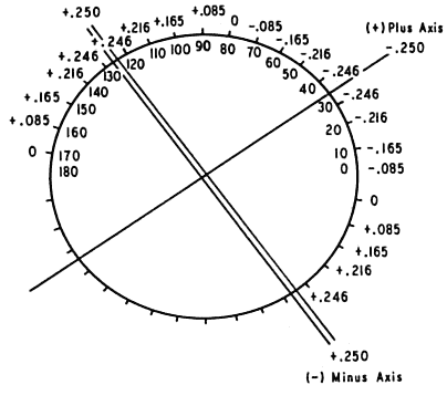
Fig. 8. The 0.25-D cross cylinder. Minus axis is a double line. Power is indicated at each 10° meridian. Axes straddle 170° meridian. (Int Ophthalmol Clin 11:131, 1971)

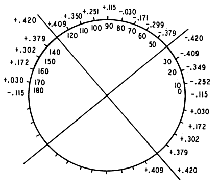
Fig. 9. + 0.420 D sph-0.840 D cyl × 130°. Resultant of superimposing Figure 5 (secondary astigmatism) and Figure 8 (cross cylinder with minus axis farther from 180°). (Int Ophthalmol Clin 11:131, 1971)

Figure 10 shows the cross cylinder in the second position with axes reversed; the minus cylinder axis is represented by a double line. Superimposing Figure 5 (the secondary astigmatism) and Figure 10 yields Figure 11, the tertiary astigmatism produced with the cross cylinder in the following position: + 0.083 D sph-0.166 D cyl × 30°. Notice that in the second position of the cross cylinder, the powers seem to neutralize each other at each meridian, whereas in the first position they augment each other. The patient will readily choose the position of the cross cylinder that produces the weaker tertiary astigmatism as being less distorting or clearer. This is the position of the cross cylinder depicted in Figure 10. Rotating the axis of the correcting cylinder toward the minus axis of the cross cylinder will bring the correcting cylinder axis closer to 180°. This is the reason for the following rule: “The correcting cylinder is rotated toward the axis of the cross cylinder of similar sign in the clearer position.” If a plus cylinder were used for correction, the cylinder would be rotated toward the plus axis of the cross cylinder; similar results would be obtained.

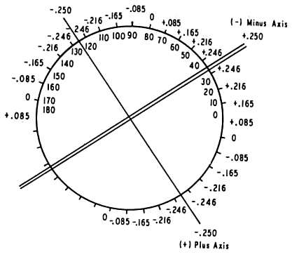
Fig. 10. The 0.25-D cross cylinder with axes reversed from positions in Figure 8. Minus axis is marked as a double line. Axes straddle 170° meridian. (Int Ophthalmol Clin 11:131, 1971)

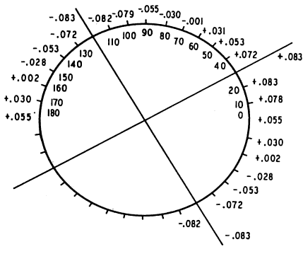
Fig. 11. + 0.083 D sph-0.166 D cyl × 30°. Resultant of superimposing Figure 5 (secondary astigmatism) and Figure 10 (cross cylinder with minus axis closer to 180°). Compare with Figure 9. (Int Ophthalmol Clin 11:131, 1971)

When the correcting cylinder arrives at 180° the secondary astigmatism disappears. The cross cylinder itself now forms a secondary astigmatism as it straddles the axis of the correcting cylinder (which is now at the correct axis). When the blurring produced in the two positions of the cross cylinder is equal, the end point is established. Notice that the cross cylinder produces little shift in the axis of the secondary astigmatism. It instead augments the power of the tertiary astigmatism produced in one position and diminishes it in another.

In summary, we have done two things:

  1. By misplacing the axis of the correcting cylinder, we have created a secondary astigmatism.
  2. By using the cross cylinder, we have augmented or diminished the power of this new astigmatism in order to ascertain which direction the correcting cylinder must be rotated to approach the true axis of astigmatism.

You may wonder why we become involved with “tertiary astigmatism” when we might use the blurring induced by the secondary astigmatism to determine the correct axis. The following method may be used3:

  1. Make a temporary overcorrection with the trial cylinder.
  2. Rotate the trial cylinder in the frame a few degrees to either side of the assumed axis.
  3. Ask the patient to choose the clearer position; he or she will readily recognize the sudden shift in the resultant cylinder axis as the correct axis is passed, forming a secondary astigmatism.

There are, however, pitfalls to this procedure.8 The examiner must closely approximate the necessary cylindric power. Performing this test with a slight overcorrection is desirable to enhance the end point. If too strong a cylinder is employed, the degree the cylinder must be rotated in order to achieve a significant shift in axis is increased. This will reduce the power of the resultant cylinder, negating somewhat the crisp end point of the test. If too weak a cylinder is employed, the shift in axis with rotation of the correcting cylinder will not be sufficient to make the test results definitive. Linksz8 found this rotation method far more accurate with the Reagan-Lancaster dial than with Snellen letters.

Rotation of the correcting cylinder before the eye to determine the correct axis of astigmatism is highly accurate when the correct or slightly stronger cylinder power is selected as the trial lens and the Reagan-Lancaster dial is used as the test target. No similar reservations need be made regarding the use of the cross cylinder in determining the astigmatic axis. It is a highly accurate and reproducible technique.

Back to Top
DETERMINATION OF CYLINDER POWER
When the correct cylinder axis has been found, attention is turned to determining the proper cylinder power. The cross cylinder is placed in front of the correcting cylinder with either axis (plus or minus) parallel to and superimposed on the axis of the correcting cylinder. Snellen letters, preferably 20/40 or better, are used. The cross cylinder is then twirled. The plus and minus axes of the instrument successively come to overlie the axis of the correcting cylinder. Cylinder power is changed according to the patient's selection. For example, if the plus axis overlying the correcting cylinder axis produces the clearer image, more plus cylinder or less minus cylinder is placed in the trial frame. This is continued until equal clarity (or equal blurredness) is noted on twirling the cross cylinder.

The following simple example demonstrates exactly how this occurs. In the previous section, our model needed a -1.00 D cyl × 180° for total correction. From our retinoscopy, we have decided that the correcting cylinder is -0.75 D cyl × 180°. Once we have determined the correct axis, we perform the maneuvers outlined earlier. With the plus axis of the cross cylinder at 180°, we have the following:

  -0.75 D cyl × 180°
  correcting cyl
  + 0.25 D cyl × 180°-0.25 D cyl × 90°
  cross cyl
  -0.50 D cyl × 180°-0.25 D cyl × 90°
  resultant

With the minus axis of the cross cylinder at 180°, we have the following:

  -0.75 D cyl × 180°
  correcting cyl
  -0.25 D cyl × 180°+ 0.25 D cyl × 90°
  cross cyl
  -1.00 D cyl × 180°+ 0.25 D cyl × 90°
  resultant

With the plus cylinder axis of the cross cylinder at 180°, the resultant differs from the required 1.00 D cyl × 180° by -0.50 D cyl × 180°-0.25 D cyl × 90°; however, with the minus axis of the cross cylinder at 180°, this difference is only 0.25 D cyl × 90°. The patient will choose the second position, which offers more minus cylinder at 180°. We now add -0.25 D cyl × 180° and the correction is exact (i.e., -1.00 D cyl × 180°). We repeat the cross cylinder twirling. Since the refractive error of the eye is neutralized, blurring or clarity in the two positions of the cross cylinder will be equal; this is the end point of the test.

It has been determined2,9 that patients prefer having the vertical components of letters sharply focused and the horizontal components slightly blurred rather than the reverse (i.e., slightly blurred vertical components and sharply focused horizontal components). This may lead to a patient's choosing more minus cylinder axis 90° or plus cylinder axis 180°. For example, a patient who is fogged, with both vertical and horizontal components focused in the vitreous. He requires, a -0.25-D sphere to complete his refraction. We are completing our work with the cross cylinder (-0.25 D cyl+ 0.25 D cyl). With the minus axis at 90°, the vertical meridian falls on the retina and the horizontal meridian moves 0.25 D farther away from the retina; the reverse occurs when the cross cylinder is at 180°. The patient should report that there is equal blurring in the two positions, but many will choose the first position. The vertical meridian is in sharp focus on the retina. This problem can be minimized by avoiding fogging when using the cross cylinder technique and by relying on the condition of meridional balance (defined earlier).

Jackson, however, used the cross cylinder apparently satisfactorily with the eye fogged.3 Others2,10 have pointed out the advantage of using the cross cylinder with the eye in meridional balance.

Back to Top
PRESBYOPIA
The use of the cross cylinder in determining presbyopia and in prescribing the necessary corrective lenses was described by Jacques, an optometrist.2 The target he used was a cross printed on a card (Fig. 12); each limb of the cross was made up of three heavy black lines. The test may be performed monocularly or binocularly. The Jacques target and the appropriate cross cylinder are incorporated in the AO Phoropter (Reichert Optical Instrument Division, Leica Inc., Buffalo, New York).

Fig. 12. Jacques blur-point card. (Int Ophthalmol Clin 11:131, 1971)

The full distance correction is determined, and the cross target is placed 40 cm in front of the patient. A cross cylinder (+ 0.50 D × 180°-0.50 × 90°) is introduced before each eye. (The minus cylinder axis should be at 90°.) If the target is conjugate with the retina (i.e., if the patient can adequately accommodate to the target), the vertical bar of the cross will fall as far “behind” the retina as the horizontal bar falls in “front” of the retina. The patient will report equal clarity or blurring of the bars of the target. If, however, the patient is presbyopic (i.e., cannot accommodate enough), the horizontal bar of the cross will fall closer to the retina than will the vertical bar; the patient will report that the horizontal bar is clearer. Plus lenses are added until equal clarity (or blurring) is obtained for both bars of the cross. Overcorrection will cause the vertical bar of the cross to be clearer.

The test is based on the assumption that the patient will suspend his accommodation between the bars of the cross when the cross cylinder is introduced. The test is not valid if the patient actively accommodates on one set of lines.

One investigator11 used an elaborate optical setup to study the accommodative responses of eight young subjects with active accommodation in this test situation. The conclusion from this small sample was that little attempt was made to accommodate on a line target and that, in fact, accommodation was suspended between the horizontal and vertical test lines.

Theoretically, this should be a valid test for the detection and correction of presbyopia. In practice, however, patient responses for some authors were variable.1 Difficulty was encountered in obtaining clarity of both sets of lines. Egan,2 however, in his review of cross cylinder technique, was quite enthusiastic about the reliability of this test. I have used the test, mainly monocularly, and tend to agree that there is a variability of response among patients and in many cases the end point is not sharp. I prefer other methods for prescribing a presbyopic add.

Back to Top
ACCOMMODATION
The cross cylinder may be used to measure the amplitude of accommodation.2 It is a variation of the test for presbyopia. The patient wears his full-distance correction, and a 0.25-D or 0.50-D cross cylinder with the minus axis at 90° is placed before the patient. A Jacques blur-point cross is then placed 33 cm from the patient. If the patient is not presbyopic, the horizontal and vertical lines will appear equally clear. The card is then slowly moved toward the patient's eye, and he is asked to report when the horizontal lines appear blacker than the vertical lines. At this point, the amount of accommodation is read from a Prince rule, or it is determined from the distance between the patient's eye and the target. If the patient is presbyopic, a + 3.00-D lens is introduced, and the test is performed again; the 3 D is subtracted from the final result. As the card is brought closer to the patient's eye, he or she is forced to accommodate to keep the lines equally clear. When the accommodative reserve is exhausted, this dual clarity cannot be maintained. The lines parallel to the plus axis on the cross cylinder come to lie on or near the retina. Those parallel to the minus axis of the cross cylinder are focused behind the retina and are less clear.
Back to Top
CROSS CYLINDERS AND OTHER REFRACTIVE TECHNIQUES
Cross cylinder technique may be combined with other refractive techniques for the determination of axis and strength of the correcting cylinder.

The Reagan-Lancaster dial may be used with the cross cylinder instead of Snellen letters. After a tentative spherocylinder is selected, the patient is presented with the dial figure. The cross cylinder is placed with its axes straddling the correcting cylinder axis at 45° each and is twirled. (The techniques and principles set forth in the sections on determination of cylinder axis and power apply to the dial and cross cylinder. The difference is only in the choice of target.) The correcting cylinder is rotated toward the axis of similar sign in the clearer position of the cross cylinder. The end point is equal clarity or blurring of the lines of the dial in both positions of the cross cylinder. The cross cylinder is then rotated so that its axes successively come to overlie the correcting cylinder axis. Cylinder power is determined using the dial figure. The end point is equal clarity of all the lines of the dial.

The rotating cross may be substituted for the dial.12 For determining cylinder axis, the arms of the cross are rotated to straddle the axis of the correcting cylinder at 45° each. The axes of the cross cylinder also straddle the correcting cylinder. The usual maneuvers for determining cylinder axis are employed. The cross is rotated each time it is necessary to rotate the correcting cylinder as refinements of axis are made. The end point is equal clarity or blurring of the bars of the cross.

Cylinder power is determined by placing one limb of the cross parallel to the axis of the correcting cylinder. Cylinder power is changed appropriately until equal clarity of the bars of the cross is obtained.

The foregoing methods are not intended to be the primary technique used for the detection and correction of astigmatism. They appear to be most useful in evaluating small astigmatic errors.

Linksz8 reviewed the various reported methods and concluded that the cross cylinder test was most easily and accurately performed with Snellen letters. With dials, however, he found that individual cylinders are more effective.

An objective method for determining and correcting astigmatism has also been described.12 This involves the use of the cross cylinder with retinoscopy. Appropriate spheres are introduced with retinoscopy to create a condition of compound hyperopic astigmatism. Plus cylinders are introduced to neutralize the astigmatism. Axis may be checked by “rocking the cylinder.” As a final check for correct axis, a cross cylinder (0.12 D or 0.25 D) is introduced, straddling the axis of the correcting cylinder. It is twirled in front of the correcting cylinder, and both sides are examined by retinoscopy. The side creating the least resultant astigmatism is studied further. If the correcting cylinder axis is correct, a “with” motion will be obtained parallel to the minus axis of the cross cylinder. If this “with” motion is weak or absent, the correcting cylinder is rotated toward the plus axis of the cross cylinder until the “with” motion is clearly seen.

This, of course, is a variation of the technique of determining cylinder axis with the cross cylinder. We know that in one position of the cross cylinder we augment the tertiary astigmatism and in the other we diminish it. The position that diminishes the astigmatism is the one that the patient says is clearer, and this is the position discussed earlier. At the correct axis, the tertiary astigmatism is neutralized, leaving only the power of the cross cylinder. This is “plus” power at the minus axis and thus gives us a “with” motion on retinoscopy.

Back to Top
ASTIGMATISM
The cross cylinder may be used to determine astigmatism,2,3 particularly when its presence is in doubt. The cross cylinder is introduced over the correcting sphere with the plus cylinder first at 90° and then at 180°. If neither position provides any increased clarity for the patient, the oblique meridians are explored in a similar fashion. If some enhancement of clarity is found in any position, a correcting cylinder may be introduced at the appropriate axis and refining procedures can then be carried out.
Back to Top
REFERENCES

1. Friedman B: The Jackson crossed cylinder. Arch Ophthalmol 24:490, 1940

2. Egan JA: A resume of cross cylinder application and theory. Surv Ophthalmol 1:513, 1956

3. Jackson E: A trial set of small lenses and a modified trial size frame. Trans Am Ophthalmol Soc 4:595, 1887

4. Crisp WH: A new cross cylinder test for astigmatic axis. Am J Ophthalmol 26:571, 1942

5. Hymes C: The correlation of the phenomena of crossed and obliquely crossed cylinders with cylinder retinoscopy and clinical refraction. Trans Am Ophthalmol Soc 47:454, 1942

6. Cowan A: Refraction of the Eye, p 268. Philadelphia, Lea & Febiger, 1938

7. Prangen AD: Some problems and procedures in refraction. Arch Ophthalmol 18:432, 1937

8. Linksz A: Determination of axis and amount of astigmatic error by rotation of trial cylinder. Arch Ophthalmol 28:632, 1942

9. Williamson-Noble FA: A possible fallacy in the use of the cross cylinder. Br J Ophthalmol 27:1, 1943

10. Pascal JI: Cross cylinder tests: Meridional balance technique. Ophthalmol J 87:31, 1950

11. Westheimer G: Accommodation levels during near crossed cylinder test. Am J Optom 35:599, 1958

12. Crisp WH, Stine GH: A further, very delicate test for astigmatic axis: using the cross cylinder with an astigmatic dial and without the use of test letters. Am J Ophthalmol 32:1065, 1949

Back to Top